508258-YIM-E-0412
Johnson Controls Unitary Products 23
of the unit wiring diagram. It resets automatically. The limit
switch operates when a high temperature condition caused
by inadequate supply air flow occurs, thus shutting down
the ignition control and closing the main gas valve and
energizing the blower.
2. Pressure Switch (PS) - If the draft motor should fail, the
pressure switch prevents the ignition controls and gas
valves from being energized.
3. Flame Sensor - The flame sensor and controls are located
per Proper Flame Adjustment Figure 17. If an ignition
control fails to detect a signal from the flame sensor
indicating the pilot flame is properly ignited, then the main
gas valve will not open.
4. Rollout Switch (RS) - This switch is located in the burner
vestibule. In the event of a sustained main burner flame
rollout, it shuts off the ignition control and closes the main
gas valve.
NOTE: The manual reset Rollout Switch (RS) must be reset
before allowing furnace operation.
5. Auxiliary Limit Switch (ALS) - This control is located
inside the heat exchanger compartment and is set to open
at 160°F. It is a manual reset switch. If ALS trips, then the
primary limit (LS) has not functioned correctly. Replace the
primary limit LS.
Cooling Sequence Of Operations
When the thermostat calls for COOL, the thermostat terminals
G and Y are energized, which signals the compressor and
outdoor fan to run.
With a call for Y, the circulating fan is energized at cooling speed.
When the thermostat is satisfied, terminals G and Y are de-
energized, de-energizing the compressor and outdoor fan.
After a cool fan off delay timing of 30 seconds, the circulating
fan is de-energized.
Safety Controls
The control circuit includes the following safety controls:
1. High Pressure Switch (HP)- This switch protects against
excessive discharge pressures due to a blocked
condenser coil or a condenser motor failure (opens at 625
± 25 psig and resets at 500 ± 25 psig).
2. Low Pressure Switch (LP)- This switch protects against
loss of refrigerant charge (opens at 7 ± 3 psig and resets at
22 ± 5 psig).
The above pressure switches are specifically designed to
operate with R-410A systems. R-22 pressure switches must
not be used as replacements for the R-410A pressure
switches.
Circulating Fan
When the thermostat calls for FAN, the thermostat terminal G is
energized signaling the circulating fan to run at the selected
airflow.
If a call for COOL occurs, the circulating fan continues to run at
the cool speed.
If a call for HEAT occurs, the circulating fan switches to heat
speed after a 30 second delay.
When the thermostat ends the call for FAN, the thermostat
terminal G is de-energized, de-energizing the circulating fan.
Start-Up
Prestart Check List
Complete the following checks before starting the unit.
1. Check the type of gas being supplied. Be sure that it is the
same as listed on the unit nameplate.
2. Make sure that the vent outlet air hood has been properly
installed.
Operating Instructions
1. STOP! Read the information on the unit safety label.
2. Set the thermostat to the OFF position.
3. Turn off all electrical power to the unit.
4. DO NOT try to light the burners by hand. This appliance is
equipped with an ignition device which automatically lights
the burners.
Table 19: Ignition Control Board FLASH CODES
Flash Code Description
Heart Beat Normal Operation
2 Flashes Pressure switch open with inducer on
3 Flashes Pressure switch closed with inducer off
4 Flashes Not Used
5 Flashes Lockout from too many flame losses
6 Flashes High temperature switch open
7 Flashes Rollout switch open
8 Flashes Flame present with gas off
9 Flashes Gas valve stuck OFF or ON
10 Flashes Flame sense circuit failure
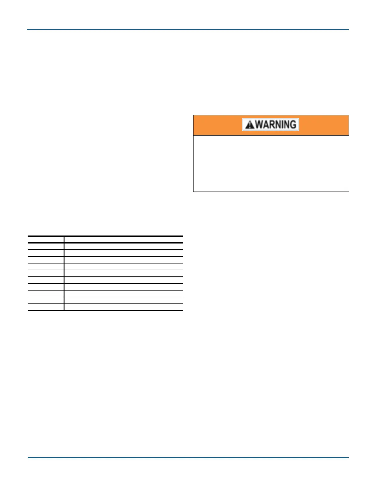
The ability to properly perform maintenance on this
equipment requires certain expertise, mechanical
skills, tools and equipment. If you do not possess
these, do not attempt to perform any maintenance
other than those procedures recommended in this
Installation Manual. Failure to heed this warning could
result in serious injury and possible damage to this
equipment.