508258-YIM-E-0412
24 Johnson Controls Unitary Products
5. Remove the access panel.
6. Turn the gas valve switch to the OFF position.
7. Wait five (5) minutes to clear out any gas. If you then smell
gas, STOP! Follow B in the information on the unit safety
label. If you don't smell gas, go to the next step.
8. Turn the gas valve switch to the ON position.
9. Replace the control access panel.
10. Turn on all electric power to the unit.
11. Set the thermostat to the desired setting.
12. If the unit will not operate, follow the instructions To Turn
Off Gas To Appliance and call your service technician or
gas supplier.
To Turn Off Gas To Unit
1. Set the thermostat to the OFF position.
2. Turn off all electric power to the appliance if service is to be
performed.
3. Remove the control access panel.
4. Turn the gas valve switch to the OFF position. DO NOT
FORCE.
5. Replace the control access panel.
Post Start Check List
After the entire control circuit has been energized and the
heating section is operating, make the following checks:
1. Check for gas leaks in the unit piping as well as the supply
piping.
2. Check for correct manifold gas pressures. See Checking
Gas Input.
3. Check the supply gas pressure. It must be within the limits
shown on rating nameplate. Supply pressure should be
checked with all gas appliances in the building at full fire. At
no time should the standby gas line pressure exceed 13.5",
nor the operating pressure drop below 4.5" for natural gas
units. If gas pressure is outside these limits, contact the
local gas utility for corrective action.
Manifold Gas Pressure Adjustment
Small adjustments to the gas flow may be made by turning the
pressure regulator adjusting screw on the automatic gas valve.
Refer to Figures 13 and 14.
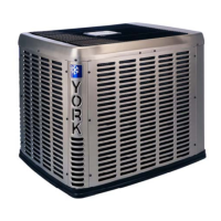
Figure 13: Single Stage Gas Valve Front
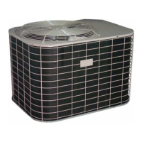
Figure 14: Two Stage Gas Valve Front
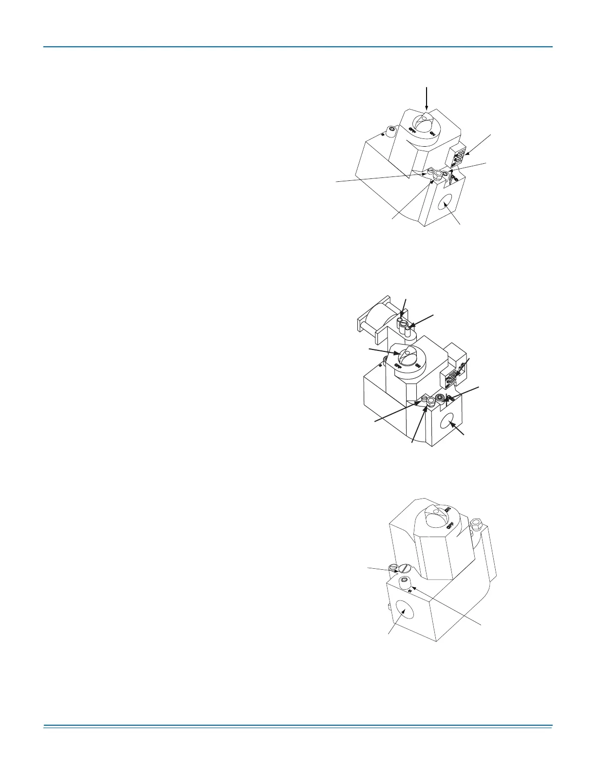
Figure 15: Single Stage Gas Valve Rear
Manual
Gas Switch
Pilot
Adjustment
(Remove Cap)
Pilot Gas
Connection
(1/4” Compression)
1/2” NPT
(Outlet)
Outlet Pressure
Tap (1/8” NPT)
Electrical
Connection
Hi Fire
(2nd Stage)
Manifold Pressure
Low Fire
(1st Stage)
Manifold Pressure
Adjustment
Electrical
Connection
½ NPT
(Outlet)
Manifold
Pressure
Tap
Pilot
Gas
Connect
Pilot
Adjustment
(Remove Cap)
Manual
Gas
Switch
Manifold Pressure
Adjustment
(Under Cap)
1/2” NPT
(Inlet)
Line Pressure
Tap (1/8” NPT)