44
2 - Installation (cont’d)
2.4 - Installation and wiring
To install the thermostat:
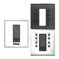
1. Lift the thermostat cover and insert a flat blade screwdriver or coin
into the slot located in the bottom center of the thermostat case and
twist 1/4 turn. Grasp the base from the bottom two corners and sepa-
rate from the thermostat. (See figure 2).
2. Swing the thermostat out from the bottom, and lift up and off the
base. Place the rectangular opening in the base over the equipment
control wires protruding from the wall and, using the base as a tem-
plate, mark the location of the two mounting holes. No leveling is
required.
3. Use the supplied anchors and screws for mounting on drywall or
plaster. Drill two 5 mm holes at the marked locations, and tap nylon
anchors flush to the wall surface and fasten.
(See figure 3).
4. Connect the wires from the existing system to the thermostat termi-
nals according to Wiring Tables 2 and 3. Push extra wire back into
the wall. Wires must be flush to the plastic base.
2.5 - Fixing the thermostat and cover to the installed based
1. Position the thermostat inside the cover and attach on the
hinsed tabs located at the top of the base.
2. Swing the thermostat and cover down, and press on the bot-
tom centre edge until they snap in place. (See figure 4).
Fig. 3 - Mounting the base
Fig. 4
2.6 - Dip Switch options and functions for ARTTP001S (SMS-1)
Positioning the DIP switches in either the ON or OFF position enables
you to choose between two different options.
The table below shows the description of the functions.
Thermostat cover lock
If desired, insert the plastic lock piece
into the bottom of the mounted base.
The ends of the lock piece should fit
snugly under the lock pins extending
from the bottom of the mounted
base. The tab in the middle of the
lock piece should extend downward
from the mounted base.
To release the locking mechanism,
press the lock piece up and into the
base while gently prying open the
cover at the same time. Use caution
to avoid cracking the thermostat
base or cover.
4 events per day
Smart fan disabled
4 minutes
(minimum on)
Keyboard unlocked
Fan with heat/cool call
Single stage
LED 1 icon off
LED 2 icon off
2 events per day
Smart fan enabled
2 minutes (minimum
on)
Keyboard locked
Fan with plenum switch
Multistage
LED 1 icon
(dirty filters)
LED 2 icon
(Compressor fault)
S w i t c h / J u m p e r
s e l e c t i o n s
1 2 or 4 events per day
2 Smart fan ON/OFF
3 Heat/Cool: 4 or 2 min.
minimum on and off
4 Keyboard
unlocked/locked
5 Fan immediate with
heat call; or with ple-
num switch
6 Single stage/
Multistage
7 LED1 icon OFF/ON
8 LED2 icon OFF/ON
Description
2 events include day and night
4 events include morning, day, evening
and night
Smart fan on will run fan continuously in
occupied mode but cycle the fan in unoc-
cupied mode with a call for heat or cool.
Allows selection of minimum on/off time for
compressors on heating and cooling.
Allows user to disable buttons to prevent
tampering
Allows selection of immediate fan run
with heat call or run upon activation of
plenum switch
Allows selection of multiple stage heating
or cooling
Optional selection: LCD icon comes on
with LED1 (dirty filters)
Optional selection: LCD icon comes on
with LED2 (compressor fault)
Snap Plastic
Lock into
p l a c e .
P l a s t i c
Lock Pin
ARTTP001S (SMS-1)
 Loading...