66
3 - Wiring (cont’d)
☛ Use only copper conductors only. Section > 1mm
2
.
* Only used on RTH-B, SOH-B and SCOH-B with Rol-on board.
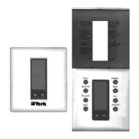
3.4 - Connections between thermostat and equipment
terminals - A R T T P 0 0 2 S
3.3 - Connections between thermostat and equipment
terminals - A R T T P 0 0 1 S
Thermostat Unit
Description
terminal terminal
W 2 W 2 Energises on a call for 2nd stage heat
Y 2 Y 2 Energises on a call for 2nd stage cool
W1 W1 Energises on a call for 1st stage heat
Y1 Y1 Energises on a call for 1 s t stage cool
G G Energises the fan circuit
R R 24 VAC Live from HVAC unit
24V 24 VAC live
24V(c) B 24 VAC common
O
Energises 4- way valve in cooling mode
B - -
LED1 -
LED2 X Refrigerant circuit fault
RS2 - Remote Sensor (option).
RS1
RS+V
No
Contacts changeover in occupied mode
COM
NC
Thermostat Unit
Description
terminal terminal
W 2 W 2 Energises auxiliary heat as 2nd stage
emergency heat
Y 2 Y 2 Energises on a call for 2nd stage heat
or cool
W1 W1 Energises
auxiliary heat as
1st stage
emergency heat
Y1 Y1 Energises on a call for 1 s t stage heat
or cool
G G Energises the fan circuit
R R 24 VAC Live from HVAC unit
24V 24 VAC live
24V(c) X 24 VAC common
O O
Energises 4- way valve in cooling mode
B B * Energises 4 way valve in heating mode
LED1 optional Dirty filters
LED2 LED2* Refrigerant circuit fault
RS2 - Remote Sensor (option).
RS1
RS+V
No
Contacts changeover in occupied mode
COM
NC
 Loading...