55
2 - Installation (cont’d)
3 - Wiring
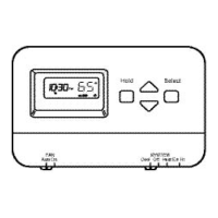
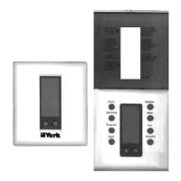
3.1 - Thermostat ARTTP001S terminals
☛ Jumper between 24V and R must be installed. ☛ Jumper between 24V and R must be installed.
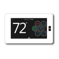
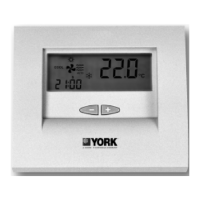
3.2 - Thermostat ARTTP002S terminals
2.7 - DIP switch options and functions for ARTTP002S (SHP-2)
Factory settings
4 events per day
Smart fan disabled
4 minutes
(minimum on)
Keyboard unlocked
Normal
Single stage
LED 1 icon off
LED 2 icon off
2 events per day
Smart fan enabled
2 minutes (minimum
on)
Keyboard locked
Not used
Multistage
LED 1 icon
(dirty filters)
LED 2 icon
(Compressors fault)
Description
2 events include day and night
4 events include morning, day, evening
and night
Smart fan on will run fan continuously on
occupied mode but cycle the fan in unoc-
cupied mode with a call for heat or cool.
Allows selection of minimum on/off time for
compressors on heating and cooling.
Allows user to disable buttons to prevent
tampering
Not used
Allows selection of multiple stage heating
or cooling
Optional selection: LCD icon comes on
with LED1 (dirty filters)
Optional selection: LCD icon comes on
with LED2 (compressor fault)
S w i t c h / J u m p e r
s e l e c t i o n s
1 2 or 4 events per day
2 Smart fan ON/OFF
3 Heat/Cool: 4or 2 min.
minimum on and off
4 Keyboard
unlocked/locked
5 Not used
6 Single stage/
Multistage
7 LED1 icon OFF/ON
8 LED2 icon OFF/ON
 Loading...