Do you have a question about the York DGAA056BDTA and is the answer not in the manual?
Details on voltage, breaker, thermostat circuit, and gas valve inlet specifications.
Compliance with national and local codes for manufactured homes, RVs, and Canadian installations.
Instructions for derating furnace input based on elevation above sea level.
Required clearances from combustible material for alcove or closet installations.
Specific conditions for floor and ceiling return air systems in closet installations.
Guidelines for designing supply duct systems for proper air distribution and static pressure.
Clearance requirements for closet doors with 5 inches or more of free area.
Clearance requirements for closet doors with 1 to 5 inches of free area.
Clearance requirements for closet doors with less than 1 inch of free area.
Steps for installing a roof jack in a new home installation.
Recommendations for roof jack extensions in areas with heavy snow accumulation.
Procedures for properly locating and cutting the ceiling and roof opening for the roof jack.
Steps for securing the roof jack to the roof and ensuring a watertight seal.
Diagrams and tables showing dimensions and part numbers for duct connectors.
Detailed steps for attaching the duct connector using screws.
Detailed steps for attaching the duct connector using tabs.
Instructions for securely connecting the roof jack assembly to the furnace.
Methods for securing the furnace to the floor using screws or other fasteners.
Procedure for connecting the 115 VAC power supply wires to the unit.
Procedure for connecting low-voltage thermostat wires to the furnace control.
Guidelines for thermostat placement and wiring diagrams for heat-only and heat-cool.
Detailed wiring diagram for DGPH056, DGPH070, DGPH077 models.
Detailed wiring diagram for DGPH090 model.
Detailed wiring diagrams for DGPA056, DGPA070, DGPA077 models.
Detailed wiring diagram for DGPA090 model.
Detailed wiring diagrams for DGAA and DGAH models.
Procedure for sizing, installing, and leak-testing the gas supply piping.
Instructions for pilot adjustment and observing burner ignition and flame.
Troubleshooting steps for common furnace operational issues.
Instructions for installing the upper and lower furnace access doors.
Considerations for installing the furnace with an air conditioning unit.
List of replacement parts and their corresponding part numbers for DGAA models.
List of replacement parts and their corresponding part numbers for DGAH models.
List of replacement parts and their corresponding part numbers for DGPA models.
List of replacement parts and their corresponding part numbers for DGPH models.
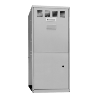
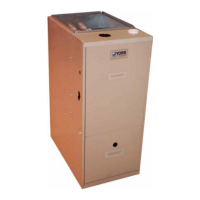
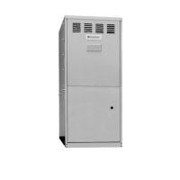
This manual describes the installation and operation of a sealed combustion downflow gas furnace, specifically models DGAA, DGAH, DGPA, and DGPH. These furnaces are designed for use in manufactured (mobile) homes, recreational vehicles & park models, and modular homes & buildings.
The device is a sealed combustion downflow gas furnace, primarily designed for heating. Some models (DGAA, DGPA) are also "A/C Ready," meaning they are designed to integrate with air conditioning systems. The furnace draws combustion air from outside the living space and vents exhaust gases outside, ensuring safe operation within enclosed environments like manufactured homes. The "downflow" design indicates that heated air is distributed downwards into the ductwork.
The manual provides detailed specifications for various models, including input and output BTUH (British Thermal Units per Hour), electrical power supply requirements, and gas valve inlet size.
Models DGAA (Automatic Ignition with Built-in Coil Cabinet - 4 Ton - A/C Ready):
Models DGPA (Standing Pilot - with Built-in Coil Cabinet - 3 Ton - A/C Ready):
Models DGPH (Standing Pilot - with Built-in Coil Cabinet - 3 Ton - No A/C Controls):
Models DGAH (Automatic Ignition - Heating Only - No Coil Cabinet):
Electrical Specifications (Common to all models):
Gas Pressure Requirements:
High Altitude Deration: For elevations above 2,000 feet, the furnace input must be derated by 4% for each 1,000 feet of elevation. This is achieved by reducing the orifice size. Specific orifice sizes for various altitudes and BTUH inputs are provided in a deration chart. In Canada, for elevations from 2000 to 4500 feet, deration is achieved by reducing gas manifold pressure to 3.0" W.C. for natural gas and 9.0" W.C. for LP gas.