8
P5417054
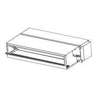
4. Installation Location
1. Install the indoor unit at a proper distance from the
walls as shown at right.
2. Install the indoor unit with sufcient space around it for operation and maintenance access as shown below.
Do not leave combustible materials inside the service space of the indoor unit.
Piping Connection Piping Connection Piping Connection
Min.
3-15/16
Min.
3-15/16
Min.
19-11/16
Min.
19-11/16
Min.
3-15/16
Min.
3-15/16
Min.
19-11/16
Min.
3-15/16
Min.
3-15/16
Min.
19-11/16
Min.
118-1/8
Min.
94-1/2
(2400)
Unit: inch (mm)
Service Sapce
(500) (500)
(100)
(100)
(3000)(500)
(500)
(100)
(100)
(100)
(100)
Distance from Wall Side
Unit: inch (mm)
Piping
Connection
Side
Min. 59-1/16 (1500)
Min. 59-1/16 (1500)
Min. 59-1/16 (1500)
Min. 59-1/16 (1500)
2. Do not insert or leave any foreign objects inside the indoor unit and verify that no foreign objects
remain inside in the indoor unit before the installation and Test Run. Failure to do this can result in
equipment failure and damage to the unit.
3. Necessary Tools and Instrument List for Installation
NOTE:
Use tools and measuring
instruments (vacuum pump, gas
hose, charging cylinder, and
manifold gauge) exclusively for
the refrigerant R410A.
No. Tool No. Tool
1 Handsaw 11 Wrench
2 Philips Screwdriver 12 Charging Cylinder
3 Vacuum Pump 13 Manifold Gauge
4 Refrigerant Gas Hose 14 Wire Cutter
5 Megohmmeter 15 Gas Leak Detector
6 Copper Pipe Bender 16 Level
7 Manual Water Pump 17 Clamp for Solderless Terminals
8 Copper Tube Cutter 18 Hoist (for Indoor Unit)
9 Brazing Kit 19 Ammeter
10 Hexagonal Wrench 20 Voltage Meter
The decorative panel, controller, and branch piping are optional accessories and are not included with the
indoor unit. If necessary, please contact your contractor.
 Loading...