JOHNSON CONTROLS
7
FORM 160.69-O1
ISSUE DATE: 9/30/2012
LIST OF FIGURES
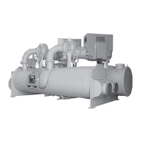
FIGURE 1 - Model YD Chiller ....................................................................................................................................9
FIGURE 2 - Chiller Operation Flow Chart ...............................................................................................................15
FIGURE 3 - Optiview™ Control Center ................................................................................................................... 25
FIGURE 4 - Home Screen .......................................................................................................................................30
FIGURE 5 - System Screen ....................................................................................................................................33
FIGURE 6 - Evaporator Screen ...............................................................................................................................35
FIGURE 7 - Condenser Screen ...............................................................................................................................38
FIGURE 8 - Refrigerant Level Control Screen ........................................................................................................40
FIGURE 9 - Main Compressor Screen .................................................................................................................... 42
FIGURE 10 - Compressor 1 Screen ........................................................................................................................44
FIGURE 11 - Compressor 2 Screen ........................................................................................................................ 46
FIGURE 12 - Proximity Probe Calibration Screen ...................................................................................................48
FIGURE 13 - Pre-Rotation Vanes Calibration Screen ............................................................................................. 50
FIGURE 14 - Variable Geometry Diffuser 1 Screen ................................................................................................51
FIGURE 15 - Variable Geometry Diffuser 2 Screen ................................................................................................53
FIGURE 16 - Variable Geometry Diffuser Setpoints Screen ...................................................................................55
FIGURE 17 - Variable Geometry Diffuser 1 Calibration Screen ..............................................................................58
FIGURE 18 - Variable Geometry Diffuser Setpoints Screen ...................................................................................59
FIGURE 19 - Hot Gas Bypass Screen ....................................................................................................................60
FIGURE 20 - Surge Protection Screen....................................................................................................................62
FIGURE 21 - Surge Protection Screen (Single Compressor Operation) .................................................................64
FIGURE 22 - Surge Protection Screen (Dual Compressor Operation) ...................................................................67
FIGURE 23 - Capacity Compressor Cycling ...........................................................................................................69
FIGURE 24 - Oil Sump Screen................................................................................................................................73
FIGURE 25 - Oil Pump 1 Screen.............................................................................................................................75
FIGURE 26 - Oil Pump 2 Screen.............................................................................................................................77
FIGURE 27 - Electro-Mechanical Starter Screen .................................................................................................... 79
FIGURE 28 - Motor Lubrication Screen...................................................................................................................83
FIGURE 29 - Setpoints Screen ...............................................................................................................................86
FIGURE 30 - Setup Screen ..................................................................................................................................... 89
FIGURE 31 - Schedule Screen ...............................................................................................................................92
FIGURE 32 - User Screen .......................................................................................................................................94
FIGURE 33 - Comms Screen .................................................................................................................................. 95
FIGURE 34 - Printer Screen ....................................................................................................................................96
FIGURE 35 - Sales Order Screen ...........................................................................................................................97
FIGURE 36 - Operations Screen .............................................................................................................................98
FIGURE 37 - History Screen .................................................................................................................................100
FIGURE 38 - History Details Page ........................................................................................................................102
FIGURE 39 - Security Log Screen ........................................................................................................................103
FIGURE 40 - Security Log Screen ........................................................................................................................104
FIGURE 41 - Custom View Screen .......................................................................................................................105
FIGURE 42 - Custom View Setup Screen ............................................................................................................. 106
FIGURE 43 - Trend Screen ...................................................................................................................................107
FIGURE 44 - Trend Setup Screen .........................................................................................................................109
FIGURE 45 - Advanced Trend Setup Screen ........................................................................................................ 111
FIGURE 46 - Common Slots Screen ..................................................................................................................... 113
FIGURE 47 - Printer ..............................................................................................................................................135
FIGURE 48 - Communications Block Diagram......................................................................................................139
FIGURE 49 - Sample Printout (Status)..................................................................................................................140
FIGURE 50 - Sample Printout (Setpoints) .............................................................................................................142
FIGURE 51 - Sample Printout (Schedule) .............................................................................................................144
FIGURE 52 - Sample Printout (Sales Order).........................................................................................................144
FIGURE 53 - Sample Printout (History).................................................................................................................146
FIGURE 54 - Sample Printout (Security Log Report) ............................................................................................ 148
FIGURE 55 - Sample Printout (Trend Data New or Existing Points) ..................................................................... 148
FIGURE 56 - Sample Printout (Custom Screen Report) .......................................................................................148

 Loading...