JOHNSON CONTROLS
9
FORM 160.69-O1
ISSUE DATE: 9/30/2012
1
Each compressor also has a Discharge Temperature
thermistor and High Pressure safety device.
There are two Liquid Line Solenoid Valves and two
Oil Return Solenoid Valves, one for each compressor.
A lockout can be performed on a compressor to pre-
vent it from running. Only one compressor at a time
can be locked out.
Two CM-2 Current Boards, one for each compressor
motor, provides motor Overload and Power Fault pro-
tection.
The Oil System consists of a common Oil Sump for
both compressors. A single Oil Heater maintains prop-
er Sump temperature when both compressors are shut-
down. This temperature is monitored by the Oil Tem-
perature Thermistor. There are two Oil pumps, one for
each compressor. Each is driven by a Variable Speed
Oil Pump Drive. The oil pressure is monitored by a
common Sump oil pressure transducer monitoring the
low side pressure. Two Pump oil pressure transduc-
ers, one for each compressor, monitor the high side oil
pressure for each compressor.
SECTION 1 – DESCRIPTION OF SYSTEM
AND FUNDAMENTALS OF OPERATION
SYSTEM OPERATION DESCRIPTION
The following is a high level description of the chill-
er control. It describes the overall operation. Control
Center components, chiller components and program-
mable setpoints are referenced. Refer to Figure 2 on
page 15 to view the chiller operation flowchart.
The YD dual compressor chiller consists of one evapo-
rator, one condenser, two oil pumps and two compres-
sors. Other than capacity control, the basic operation is
similar to a standard YK Centrifugal Chiller.
The use of two compressors requires valves on the dis-
charge line of each compressor. When a compressor
is shutdown, its discharge valve is closed to prevent
compressor backspin due to a gas flow from the run-
ning compressor. An end switch at both the closed and
open positions provides indication of full open and
full closed positions. The valves can be manually con-
trolled.
Each compressor Pre-rotation Vane assembly is
equipped with a potentiometer to provide vane posi-
tion. A calibration procedure assures displayed posi-
tion accuracy. The vanes can be manually controlled.
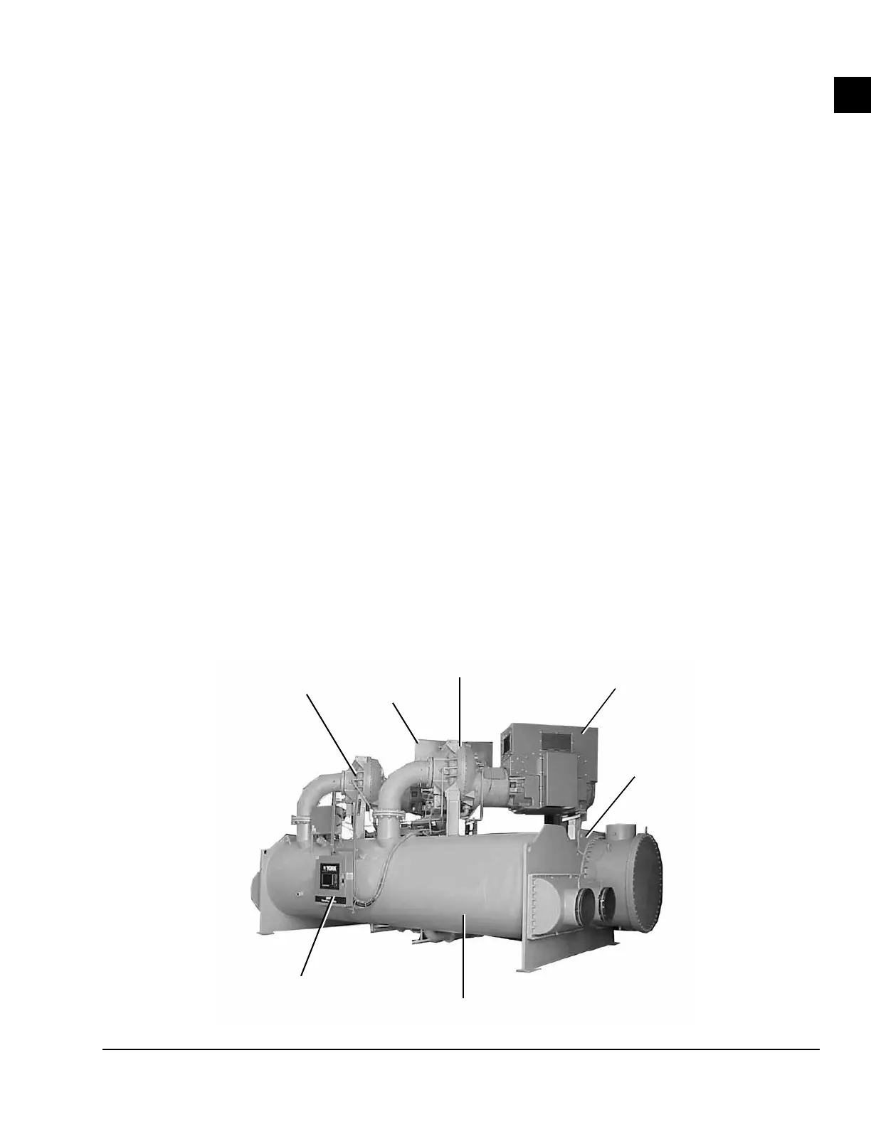
FIGURE 1 - MODEL YD CHILLER
COMPRESSOR 1
COMPRESSOR 2
MOTOR 1
MOTOR 2
CONTROL
CENTER
EVAPORATOR
CONDENSER
LD08634
 Loading...


