R-410A
MODELS:
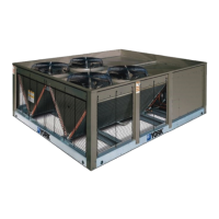
YD360 Thru 600
30 - 50 Ton
60 Hertz
5012886-YIM-B-0517
TABLE OF CONTENTS
Nomenclature . . . . . . . . . . . . . . . . . . . . . . . . . . . . . . . . . . . . . 2
General . . . . . . . . . . . . . . . . . . . . . . . . . . . . . . . . . . . . . . . . . . 2
Renewal Parts . . . . . . . . . . . . . . . . . . . . . . . . . . . . . . . . . . . . . 3
Agency Approvals . . . . . . . . . . . . . . . . . . . . . . . . . . . . . . . . . . 3
Inspection . . . . . . . . . . . . . . . . . . . . . . . . . . . . . . . . . . . . . . . . 3
Physical Data . . . . . . . . . . . . . . . . . . . . . . . . . . . . . . . . . . . 4
Installation . . . . . . . . . . . . . . . . . . . . . . . . . . . . . . . . . . . . . . . . 5
Limitations . . . . . . . . . . . . . . . . . . . . . . . . . . . . . . . . . . . . . . 5
Location. . . . . . . . . . . . . . . . . . . . . . . . . . . . . . . . . . . . . . . . 5
Clearances . . . . . . . . . . . . . . . . . . . . . . . . . . . . . . . . . . . . . 7
Rigging . . . . . . . . . . . . . . . . . . . . . . . . . . . . . . . . . . . . . . . . 7
Phasing . . . . . . . . . . . . . . . . . . . . . . . . . . . . . . . . . . . . . . . . 8
Electrical Data . . . . . . . . . . . . . . . . . . . . . . . . . . . . . . . . . . . 9
Refrigerant Mains . . . . . . . . . . . . . . . . . . . . . . . . . . . . . . . 10
Piping And Electrical Connection Sizes . . . . . . . . . . . . . . 16
Piping And Electrical Connections . . . . . . . . . . . . . . . . . . 17
Start-Up . . . . . . . . . . . . . . . . . . . . . . . . . . . . . . . . . . . . . . . . . 17
Crankcase Heater . . . . . . . . . . . . . . . . . . . . . . . . . . . . . . . 17
Operation . . . . . . . . . . . . . . . . . . . . . . . . . . . . . . . . . . . . . . . 18
Sequence of Operation . . . . . . . . . . . . . . . . . . . . . . . . . . . 18
Smart Equipment™ Control Board Navigation Components 20
Troubleshooting . . . . . . . . . . . . . . . . . . . . . . . . . . . . . . . . . . 20
Smart Equipment™ Firmware Version 3.2 Basic Unit Control
Board Navigation Examples:. . . . . . . . . . . . . . . . . . . . . . . 21
Typical Wiring Diagrams . . . . . . . . . . . . . . . . . . . . . . . . . . 31
Start-Up Sheet . . . . . . . . . . . . . . . . . . . . . . . . . . . . . . . . . . . 33
LIST OF TABLES
1 YD360 thru 600 Physical Data . . . . . . . . . . . . . . . . . . . . . 4
2 Unit Application Data . . . . . . . . . . . . . . . . . . . . . . . . . . . . 5
3 Corner Weight & Center Of Gravity (Inches) . . . . . . . . . . 6
4 Minimum Clearances . . . . . . . . . . . . . . . . . . . . . . . . . . . . 7
5 Electrical Data - Outdoor Unit . . . . . . . . . . . . . . . . . . . . . 9
6 Unit Dimensions (Inches) . . . . . . . . . . . . . . . . . . . . . . . . 14
7 Piping And Electrical Connection Sizes (30/40/50T)
(Inches) . . . . . . . . . . . . . . . . . . . . . . . . . . . . . . . . . . . . . 16
8 Electrical Power Knockout Sizes (Inches) . . . . . . . . . . . 16
9 Smart Equipment™ UCB Details . . . . . . . . . . . . . . . . . . 23
LIST OF FIGURES
1 Corner Weights & Center Of Gravity . . . . . . . . . . . . . . . . 6
2 Typical Rigging . . . . . . . . . . . . . . . . . . . . . . . . . . . . . . . . 7
3 Typical Field Wiring Diagram ND360/480 Evaporator Units,
ND600 Air Handler and M1CZ600A Evaporator Coil when
Matched with YD360/480/600 Condenser . . . . . . . . . . . 12
4 Typical ND360/480 & M1CZ600A Liquid Line Solenoid
Wiring . . . . . . . . . . . . . . . . . . . . . . . . . . . . . . . . . . . . . . . 12
5 Typical Liquid Line Solenoid Wiring . . . . . . . . . . . . . . . . 13
6 YD Unit Dimensions . . . . . . . . . . . . . . . . . . . . . . . . . . . . 14
7 30 Ton Power And Control Wiring Connections . . . . . . 15
8 40 & 50 Ton Power And Control Wiring Connections . . 15
9 30 Ton Piping Connections . . . . . . . . . . . . . . . . . . . . . . 16
10 40 & 50 Ton Piping Connections . . . . . . . . . . . . . . . . . 17
11 Fan Orientation Control Box End . . . . . . . . . . . . . . . . . . 19
12 Compressor Location . . . . . . . . . . . . . . . . . . . . . . . . . . . 20
13 Unit Control Board . . . . . . . . . . . . . . . . . . . . . . . . . . . . . 23
14 YD360 Charging Curves . . . . . . . . . . . . . . . . . . . . . . . . 29
15 YD480 Charging Curves . . . . . . . . . . . . . . . . . . . . . . . . 29
16 YD600 Charging Curves . . . . . . . . . . . . . . . . . . . . . . . . 30
17 Typical 208/230 Volt, YD360/480/600 Condensing Unit
Wiring Diagram . . . . . . . . . . . . . . . . . . . . . . . . . . . . . . . 31
18 Typical 460/575 Volt, YD360/480/600 Condensing Unit
Wiring Diagram . . . . . . . . . . . . . . . . . . . . . . . . . . . . . . . 32