5012886-YIM-B-0517
12 Johnson Controls Unitary Products
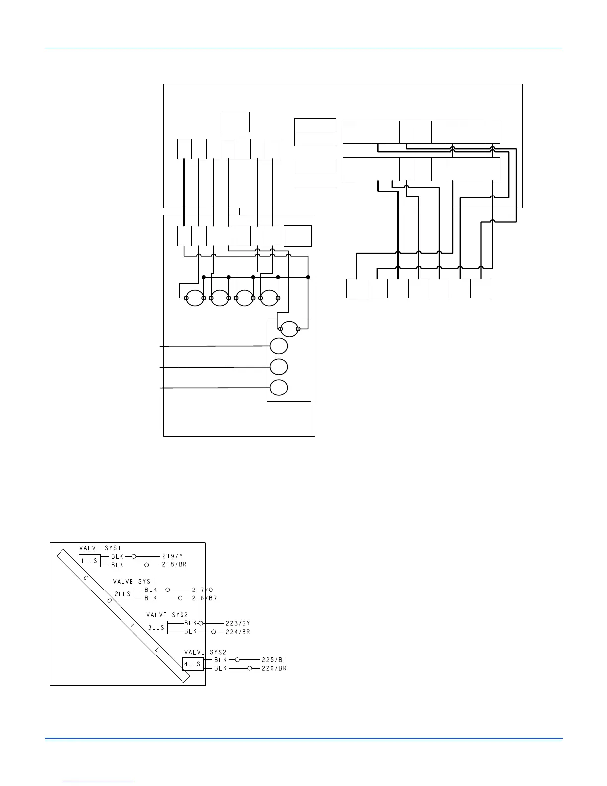
Figure 3: Typical Field Wiring Diagram ND360/480 Evaporator Units, ND600 Air Handler and M1CZ600A Evaporator Coil
when Matched with YD360/480/600 Condenser
NOTE: On non ND evaporator models, isolation relays must be
installed to avoid overloading on 75VA transformers on
the condensing unit.
Figure 4: Typical ND360/480 & M1CZ600A Liquid Line
Solenoid Wiring
NOTE: For applications on airhandlers/evaporator DX coils
other than ND360-600 certified matchups liquid line
solenoids may be required for proper operation and
refrigerant system pump out.
C S1 S2 G1 G2 S3 S4
W1 W2 Y1 G Y2 0CC CX R SD-24
SE CONTROL BOARD
THERMOSTAT CONNECTIONS
TB2
CONDENSER CONTROL BOX
EVAPORATOR CONTROL BOX
THERMOSTAT
FOUR STAGE COOL
R C Y1 Y2 G Y3 Y4
W1 W2 Y1 G Y2 0CC CX R SD-24
C S1 S2 G1 G2 S3 S4 TB1
SYSTEM 1
SYSTEM 2
UCB 2
UCB 1
1 2 3 4
POWER SUPPLY
208/230, 460
OR 575-3-60
LIQUID LINE
SOLENOID VALVES
EVAPORATOR
BLOWER MOTOR
CONTACTOR
 Loading...