41JOHNSON CONTROLS
FORM 160.80-EG1 (808)
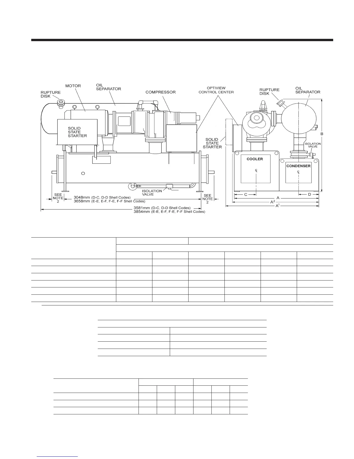
DIMENSIONS (mm)
Refer to Tables 6 and 7 on pages 26 & 27 for valid compressor/shell/motor combinations.
S4 - S5 COMPRESSOR
R-22 & R-134a UNITS
(50 and 60 Hz)
1. All dimensions are approximate. Certied dimensions are available on request.
2. Determine overall unit length by adding water box depth from table below to tube sheet length:
3. Unit height includes steel mounting plates under tube sheets. To determine overall installed height,
add 22mm for neoprene isolators (25.4 for optional spring isolators).
NOTES:
s4 CoMPrEssor s4 and s5 CoMPrEssor
shELL CodEs (EVaPorator – CondEnsEr)
d-C d-d E-E E-F F-E F-F
a – tuBE shEEt WIdth
1,880 1,880 1,880 1,943 1,994 2,057
a
1
– WIth soLId statE startEr
2,080 2,080 2,080 2,143 2,226 2,200
a
2
– oVEraLL WIdth (LEss s.s.s)
1,915 1,915 — — — —
B – oVEraLL hEIGht3
2,365 2,365 2,365 2,496 2,496 2,496
C – EVaPorator C/L
502 502 502 502 559 559
d – CondEnsEr C/L
438 438 438 470 438 470
rEFrIGErant rELIEF VaLVE ConnECtIons
VEssEL sIZE
EVaPorator
1” FPT SINGLE
CondEnsEr
1” FPT DUAL
oIL sEParator
1” FPT DUAL & 2” NOM RUPTURE DISK
tYPE CoMPaCt WatEr BoX
CooLEr CodE CondEnsEr CodE
d E F d E F
rEturn BoX
140 140 197 133 133 194
WIth VICtauLIC ConnECtIon
352 352 384 352 352 384
WIth FLanGEd ConnECtIon
365 365 397 365 365 397