30 JOHNSON CONTROLS
Dimensions – Std
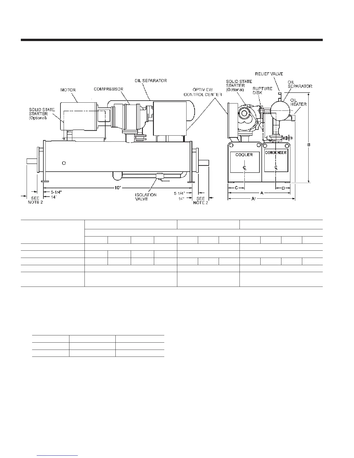
NOTES:
1. All dimensions are approximate. Certied dimensions are available on request.
2. Determine overall unit length by adding water box dimension to tube sheet length:
5-1/4” for compact return box
14” for compact water box with ANSI/AWWA C-606 couplings water nozzles
Add 1/2” to each compact water box with optional anged water nozzles
3. Unit height includes steel mounting plates under tube sheets. To determine overall height, add 7/8” for neoprene isolators
(1” for optional spring isolators).
S0 - S3 COMPRESSOR
R-22 & R-134a UNITS
(50 and 60 Hz)
REFRIGERANT RELIEF VALVE CONNECTIONS
Refer to Tables 6 and 7 on pages 26 & 27 for valid compressor/shell/motor combinations.
dIMEnsIon
s0 and s1 CoMPrEssor s2 CoMPrEssor s2 and s3 CoMPrEssor
shELL CodEs (EVaPorator – CondEnsEr)
B-B B-C C-B C-C B-B B-C C-B C-C C-d d-C d-d
a
4’–2-7/8” 5’–2-1/2” 5’–2-1/2”
a
1
4’–6-3/4” 4’–6-1/4” 4’-6-3/4” 4’–6-1/4” 5’–3-3/4” 5’–3-3/4”
B – oVEraLL hEIGht
3
5’–8-5/8” 5’–11-1/2” 5’–10-1/4” 5’–11-1/2” 5’–11-1/4” 6’–3-1/4” 6’–3-1/4” 6’–3-1/4” 6’–7-5/8” 6’–8-3/4” 6’–9-3/8”
C – CooLEr C/L
1’–1-7/8” 1’–5” 1’–5”
d – CondEnsEr C/L
0’–11-5/8” 1’–2-1/4” 1’–2-1/4”
shELL CodE EVaPorator sIZE CondEnsEr sIZE
B, C
3/4” FPT SINGLE 3/4” FPT DUAL
d
1” FPT SINGLE 3/4” FPT DUAL
CoMPrEssor CodE oIL sEParator sIZE
S0, S1 2” RUPTURE DISK & 3/4” FPT SINGLE
S2, S3 2” RUPTURE DISK & 3/4” FPT DUAL