31JOHNSON CONTROLS
FORM 160.80-EG1 (808)
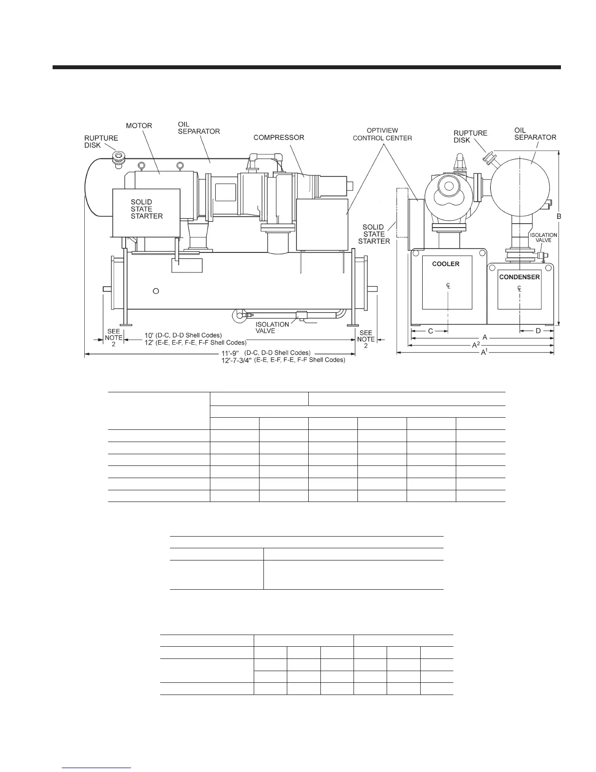
S4 - S5 COMPRESSOR
R-22 & R-134a UNITS
(50 and 60 Hz)
Refer to Tables 6 and 7 on pages 26 & 27 for valid compressor/shell/motor combinations.
1. All dimensions are approximate. Certied dimensions are available on request.
2. Determine overall unit length by adding water box depth from table below to tube sheet length:
3. Unit height includes steel mounting plates under tube sheets. To determine overall installed height,
add 7/8” for neoprene isolators (1” for optional spring isolators).
NOTES:
dIMEnsIon
s4 CoMPrEssor s4 and s5 CoMPrEssor
shELL CodEs (EVaPorator – CondEnsEr)
d-C d-d E-E E-F F-E F-F
a
6’–2” 6’–2” 6’–2” 6’–4-1/2” 6’–6-1/2” 6’–9”
a
1
6’–9-7/8” 6’–9-7/8” 6’–9-7/8” 7’–0-3/8” 7’–3-5/8” 7’–2-5/8”
a
2
6’–3-3/8” 6’–3-3/8” — — — —
B – oVEraLL hEIGht
3
7’–9-1/8” 7’–9-1/8” 7’–9-1/8” 8’–2-1/4” 8’–2-1/4” 8’–2-1/4”
C – CooLEr C/L
1’–7-3/4” 1’–7-3/4” 1’–7-3/4” 1’–7-3/4” 1’–10” 1’–10”
d – CondEnsEr C/L
1’–5-1/4” 1’–5-1/4” 1’–5-1/4” 1’–6-1/2” 1’–5-1/4” 1’–6-1/2”
rEFrIGErant rELIEF VaLVE ConnECtIons
VEssEL
SIZE
EVaPorator
CondEnsEr
oIL sEParator
1” FPT SINGLE
1” FPT DUAL
1” FPT DUAL & 2” NOM RUPTURE DISK
EVaPorator CodE CondEnsEr CodE
tYPE CoMPaCt WatEr BoX d E F d E F
RETURN BOX
WITH VICTAULIC CONN.
0’–5-1/2” 0’–5-1/2” 0’–7-3/4” 0’–5-1/4” 0’–5-1/4” 0’–7-5/8”
1’–1-7/8” 1’–1-7/8” 1’–3-1/8” 1’–1-7/8” 1’–1-7/8” 1’–3-1/8”
WITH FLANGED CONN. 1’–2-3/8” 1’–2-3/8” 1’–3-5/8” 1’–2-3/8” 1’–2-3/8” 1’–3-5/8”