Page - 16/79 AF6ZP0AL - COMBIAC0 & ACE0 - User Manual
4.2.5 Connection of the encoder
1) COMBI AC0/ ACE0 card is fit for different types of encoder. To control AC
motor with Zapi inverter, it is necessary to install an incremental encoder with
2 phases shifted of 90°. The encoder power supply can be +5 or +12V. It can
have different electronic output.
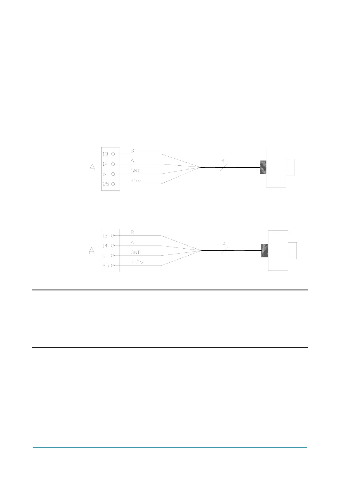
AMPSEAL CONNECTOR
A25 +5V/+12V positive of encoder power supply.
A5 GND negative of encoder power supply.
A14 A phase A of encoder.
A13 B phase B of encoder.
2) Connection of encoder with open collector output; +5V power supply.
Connection of encoder with open collector output: +12V power supply.
U VERY IMPORTANT
It is necessary to specify in the order the type of encoder used, in terms of
power supply, electronic output and n° of pulses for revolution, because
the logic unit must be set in the correct way by Zapi.
The n° of pulses revolution the controller can handle is given by the
second-last letter in the software release name (see 3.5).