Page 12
3.3 DESCRIPTION OF COMBI SEM-1 CONNECTORS
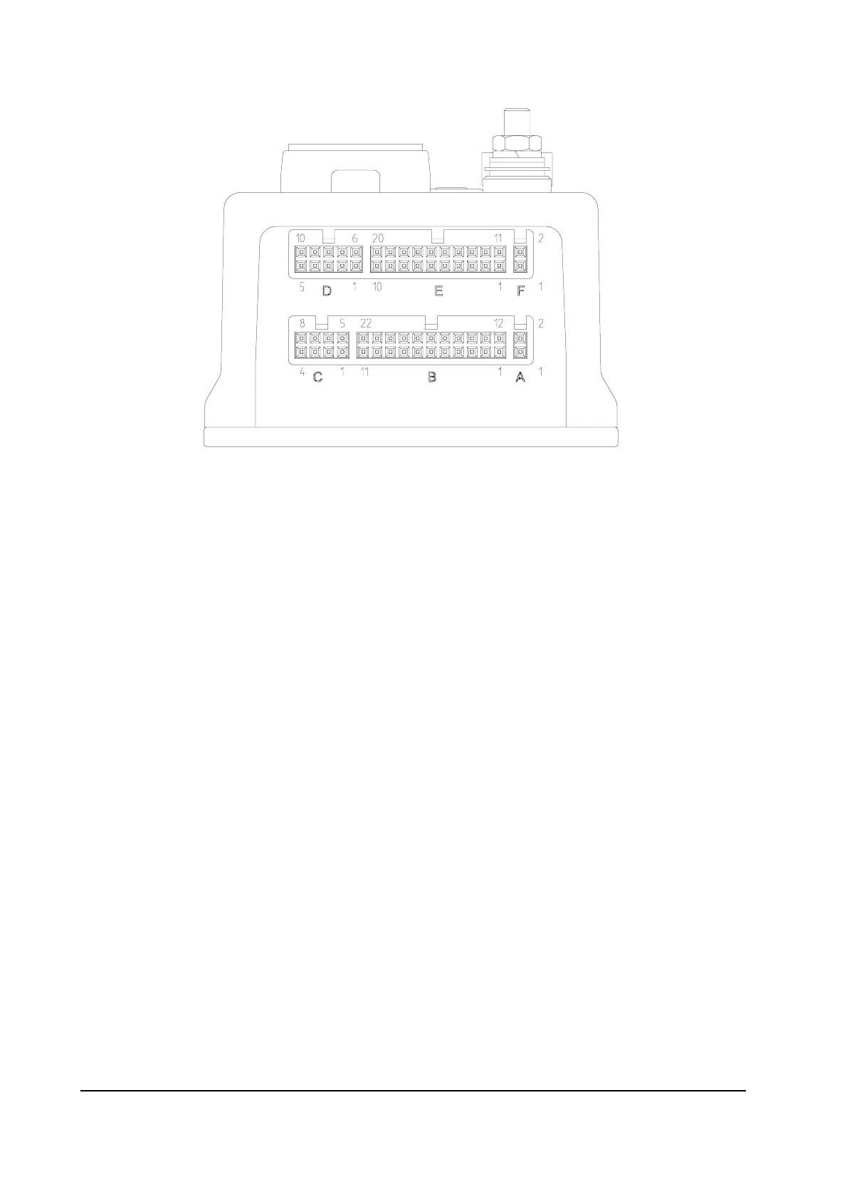
3.3.1 Connector "A" description
The "A" connector is connected by Zapi.
A1 KEY OUT This pin is connected to the pin1 of the F connector; is a key signal.
A2 BACKING This pin is connected to the pin2 of the F connector; is a backing
signal.
3.3.2 Connector "B" description
The "B" connector managed the main contactor, the brake and the electrovalves coils.
B1 + BATT Positive after the main contactor; is the electrovalves positive.
B2 NMC Negative of the main contactor
B3 -BATT Negative free for the customer.
B4 -BATT Negative free for the customer.
B5 NEB Negative of the electromechanical brake.
B6 NEVP Negative of the proportional electrovalve.
B7 NEV2-NHO Negative of the electrovalve 2; (option: negative of the horn).
B8 NEV1 Negative of the electrovalve 1.
B9 NEV4 Negative of the electrovalve 4.
B10 NEV3 Negative of the electrovalve 3.
B11 NEV5 Negative of the electrovalve 5.
B12 KEY IN Input of the Key switch signal.