Page 5
1.6 COMBI SEM-1 CHOPPER DIAGNOSIS
The microprocessor continually monitors the chopper and carries out diagnostic
procedures on the main functions.
The diagnosis is made in 4 points:
1) Diagnosis on key switch closing that checks: watch-dog, Current Sensors, VMN
point, contactor drivers, presence of a start requirement, and connection with the
Serial Tiller ok.
2) Standby Diagnosis that checks: watch-dog, VMN Point, Contactor Drivers, Current
Sensors.
3) Driving diagnosis that checks: Watchdog, VMN Point, Current, Contactor(s).
4) Continuos Diagnosis that checks: Chopper temperature, Battery Voltage.
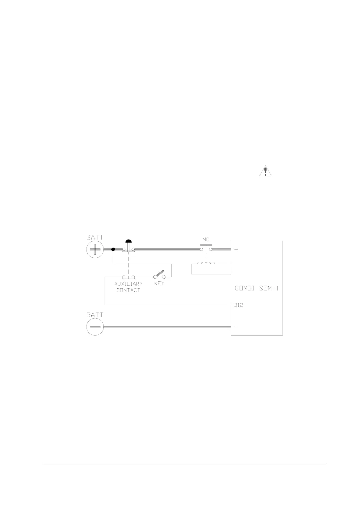
1.7 MAIN CONTACTOR AND SAFETY BUTTON
- Battery disconnection should be made according to the Diagram below.
- In order to avoid damage to the controller during the regenerative phase, the supply
to the Key Switch must be cut off at the same time.
Wiring with cut off in series to positive supply.
- An internal protection is activated when the voltage on B12 connector is greater than
30% of battery voltage, or when the key switch is opened before the battery is
opened.