AF9ZP0BA - EPS-ACW REACH TRUCK - User Manual Page - 17/90
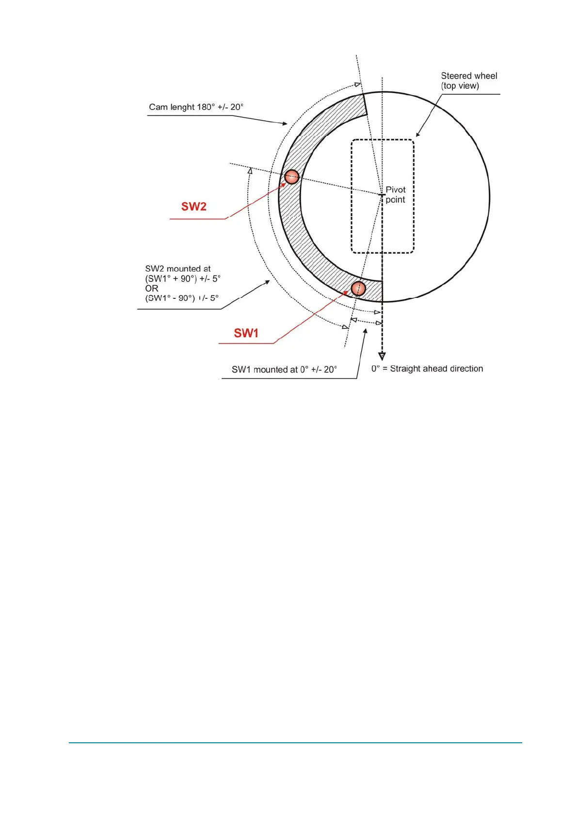
Figure 9.5.1–1
Tolerance of the SW1 (CNA#12) mounting position:...............................0°+/-20°
Tolerance of the SW2 (CNA#11) mounting position:(SW1+90°)or(SW1-90°) +/-5°
Tolerance of the cam length (see also 9.5.1.1. below) .......................180°+/-20°
9.5.1.1 Cam length and mounting criterion
When the 90 degrees switch (SW2) is involved to limit the wheel angle (option
SW2 LIMITING to ON: see 13.3.2.9), two rules should be applied when designing
the cam shape (see figures 9.5.1.1-1 and 9.5.1.1-2):
1) Length of the cam must be the sum between max CW and max CCW
angle (e.g. if the steered wheel angle must be limited to +/-82 degrees,
the cam length should be 164degrees).
2) The cam should be mounted with an offset vs. the straight ahead switch
(SW1). This offset must be the difference between 90° - max CW (or
CCW) angle.