Page 5SEM1
2.2 CONTROL UNITS
2.2.a. Microswitches.
- The microswitches must have a contact resistance lower than 0.1W and a leakage
current lower than 100µA.
- When full load connected, the voltage between the key switch contacts must be
lower than 0.1V.
- The handle microswitch must operate the electromechanical brake coil (if the
electromechanical brake is used).
- The microswitches send a voltage signal when a function request (for ex.: running
request) is made.
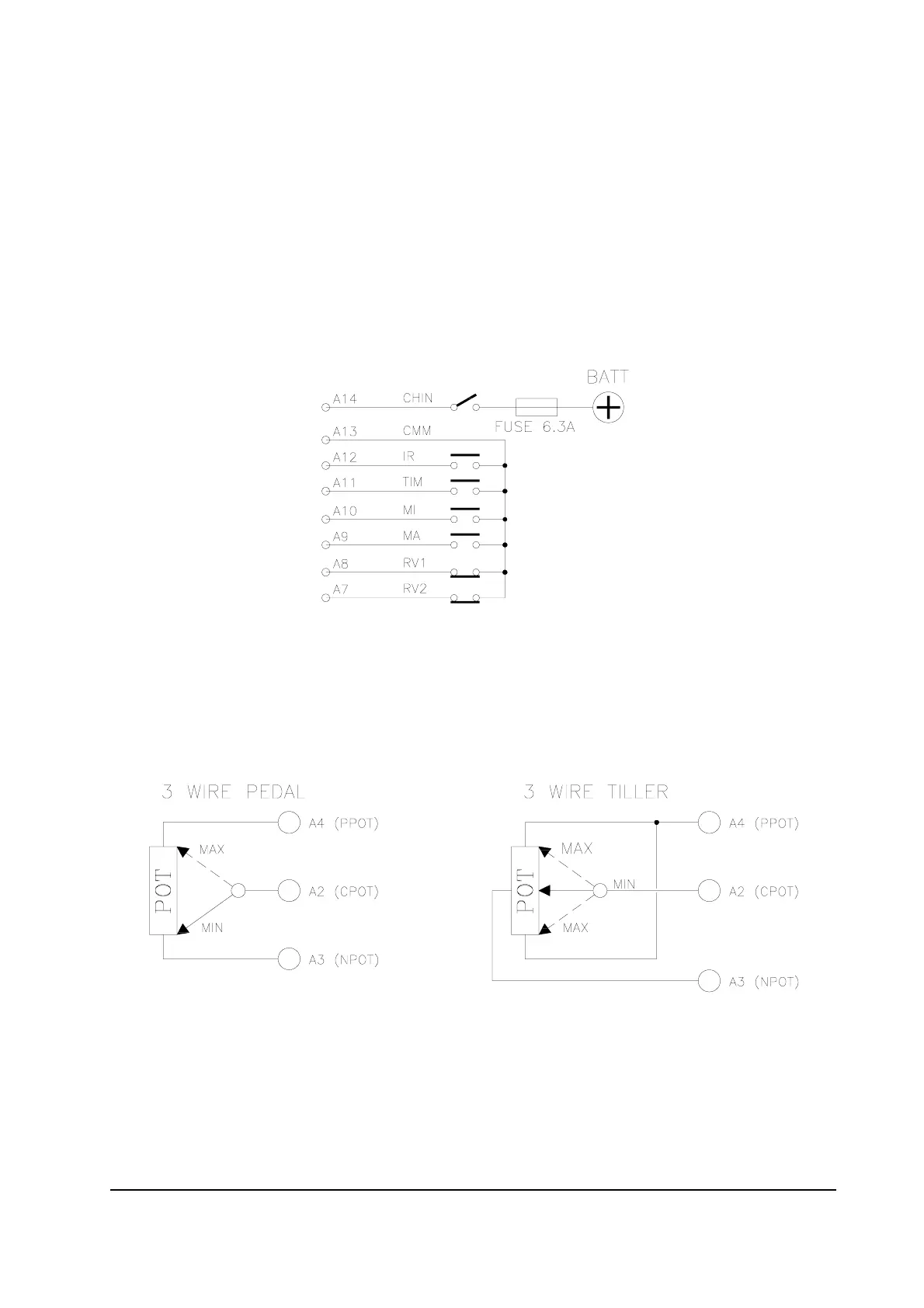
2.2.b. Potentiometer
Potentiometer should be in the 3-wire configuration.
CPOT (A2) signal ranges from 0 to 10V.
Pot. value should be in the 0.5 - 10 KW range. Faults can occour if it is outside this
range.
The procedure for automatic potentiometer signal acquisition is carried out from the
console. This makes it possible to adjust the minimum and maximum useful signal in
the respective directions. This function is indispensable when it is necessary to com-
pensate for asymmetry in the mechanical components that control the potentiometer,
especially regarding the adjustment of the minimum level.
The sequence of procedure is described in the programming console manual.