Page 4
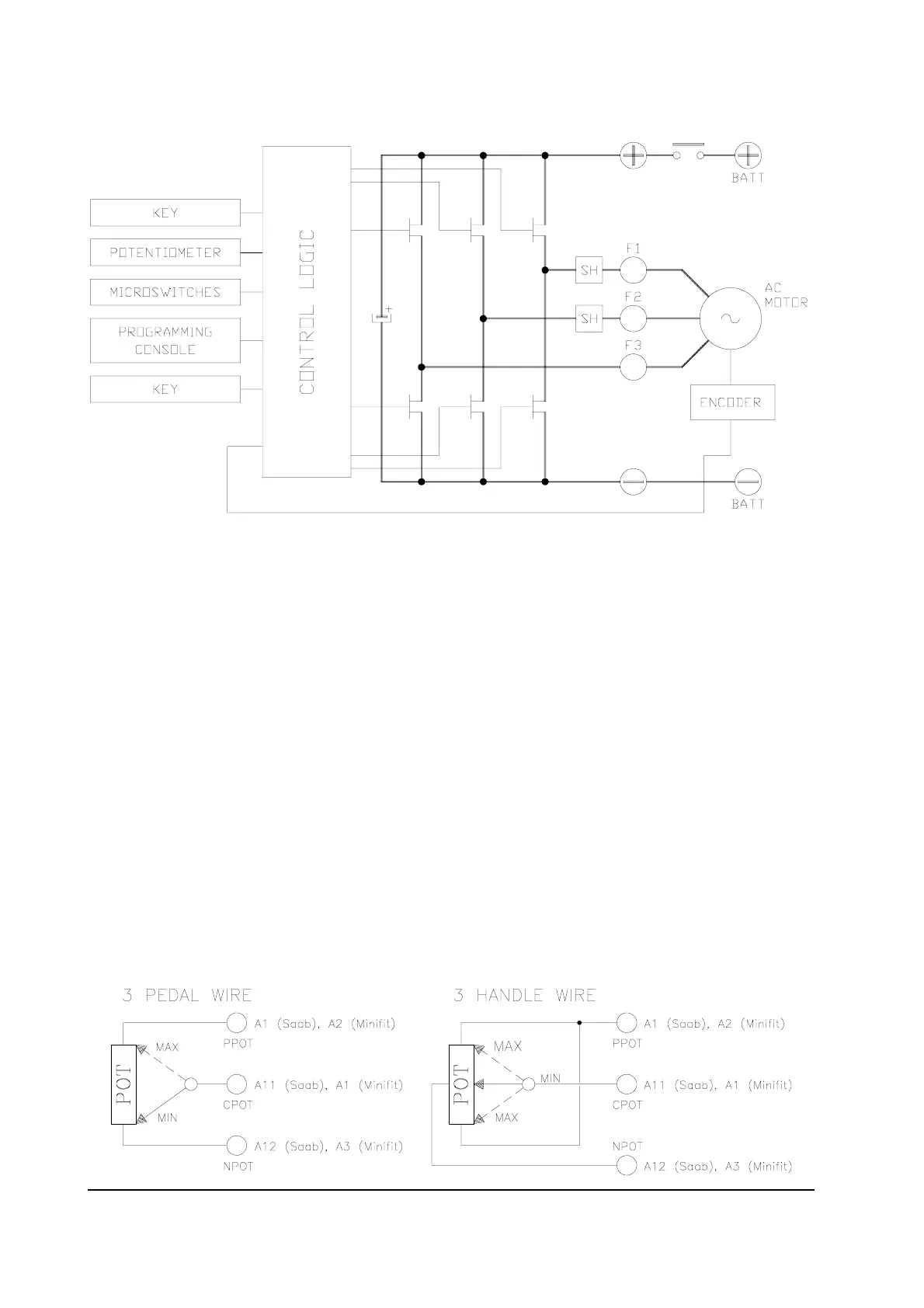
2.3 BLOCK DIAGRAM
2.4 CONTROL UNIT
2.4.a Microswitches
- The microswitches must have a contact resistance lower than 0.1W and a leakage
current lower than 100µA.
- When full load connected, the voltage between the key switch contacts must be lower
than 0.1V.
- The microswitches send a voltage signal to the microprocessor when a function request
(for ex.: running request) is made.
2.4.b Accelerator unit
The accelerator unit can consist of a potentiometer or an Hall effect device.
It should be in a 3-wire configuration.
CPOT (A11, Saab connector version; A1, Molex Minifit version) signal ranges from 0 to
10V.
Potentiometer value should be in the 0.5 - 10 Kohm range; generally, the load should be in
the 1.5mA to 30 mA range. Faults can occur if it is outside this range.