Page 11
3.4 DESCRIPTION OF CONNECTORS - TRACTION CONFIGURATION
The AC3 and AC4 have been designed to be produced with two different types of I/O
connector: One AMP SAAB 29 poles connector or six Molex Minifit connectors.
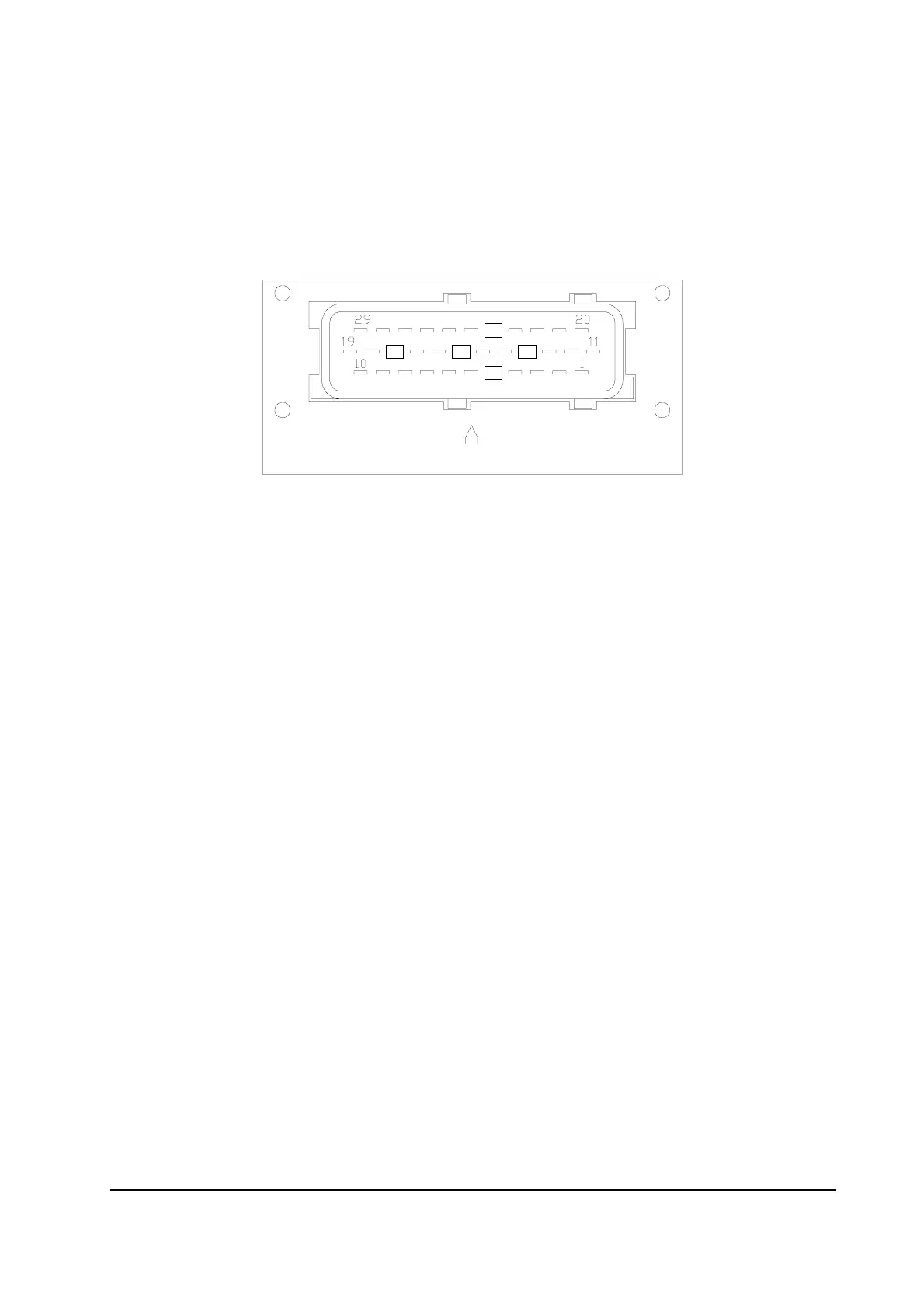
3.4.a Amp Saab connector
A1 PPOT Potentiometer positive: 10V output; keep load > 1KW.
A2 NPOTB -Batt.
A3 PTHERM Input for motor temperature sensor.
A4 NTHERM -Batt.
A5 -BATT Battery negative.
A6 NLC Negative of main contactor coil.
A7 NBRAKE Output for driving a brake or an hydraulic steering contactor coil;
drives the load to -Batt maximum current : 3A.
A8 PLC Positive of main contactor coil.
A9 CM Common of FW / BW / SR / PB / SEAT / BACK. FW / BACK. BW /
EXCLUSIVE HYDRO microswitches.
A10 KEY Connected to the power supply through a microswitch (CH) with a
10A fuse in series.
A11 CPOT Accelerator potentiometer wiper.
A12 NPOT Negative of accelerator unit, tested for wire disconnection diagnosis.
A13 CPOTB Brake potentiometer wiper.
A14 CAN-H High level CAN-BUS voltage I/O.
A15 CAN-L Low level CAN-BUS voltage I/O.
A16 FORW Forward direction request input. Must be connected to the forward
direction microswitch, active high.
A17 BW Backward direction request input. Must be connected to the back-
ward direction microswitch, active high.