DC Power Verification & Adjustment
Preparations
The exterior cover must be removed prior to proceeding. (980428-101)
The power supply must be detached from the bottom panel for access. (980428-103)
Shock Hazard
Always turn off the printer before removing the exterior cover.
The printer must be turned on after the cover is removed to perform
this procedure. See the following procedure.
20 980428-105 Rev. 1 Prelim.
DC Voltage Verification
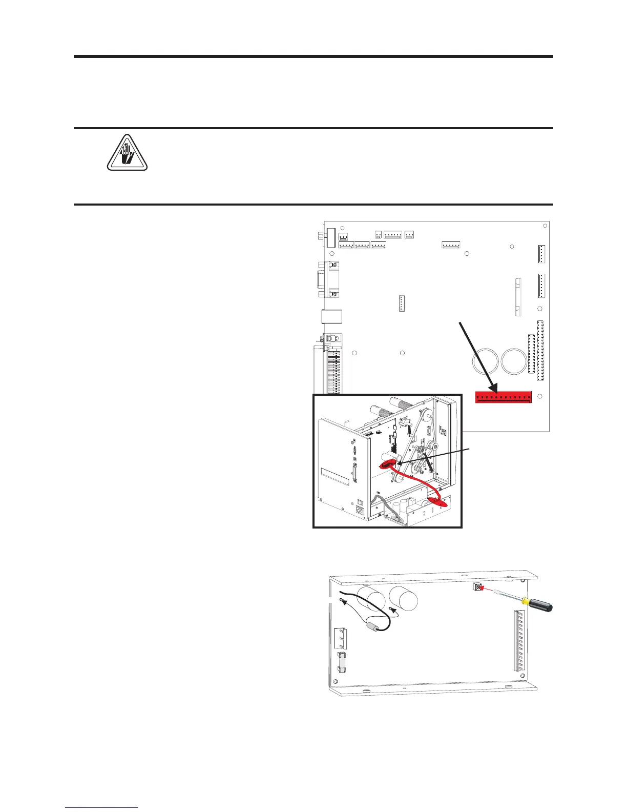
1. Disconnect the DC power cable (JP6) from
main PCBA.
2. Insert the positive voltage probe of a digital
voltmeter into one of the cable's connector
plug's socket pins with a red wire connected
to it. Insert the other probe into a socket pin
that has a black wire attached to it.
3. Turn the printer on. Measure the voltage.
The voltage should be 25 ±2 VDC. Turn
off the power.
If the voltage is out of range, the voltage
needs to be adjusted.
4. Re-attach the DC power cable to the main
PCBA.
DC Power
JP6
Disconnect the
DC Power
Cable Here
1
1
0
V
A
C
A
C
I
n
p
u
t
D
C
S
u
p
p
l
y
V
o
l
t
a
g
e
t
o
P
C
B
A
2
3
0
V
A
C
1
DC Voltage adjustment
1. Un-mount the power supply as if you were
to replacing it, see procedure 980428-103.
Leave the AC power connector plugged in.
2. Connect the voltmeter to the DC power
cable as described above.
3. Turn the power on and adjust the voltage to
25 VDC. Turn the power off.
4. Re-attach the power supply and re-tie the
main PCBA harness. Use the "Securing the
Harness" procedure.
 Loading...
