AC Power Inlet & Switch
Preparations
The exterior cover must be removed prior to proceeding. (Procedure 980428-101)
The power supply must be unscrewed from the printer's bottom plate. (Procedure 980428-103)
980428-106 Rev. 1 Prelim. 21
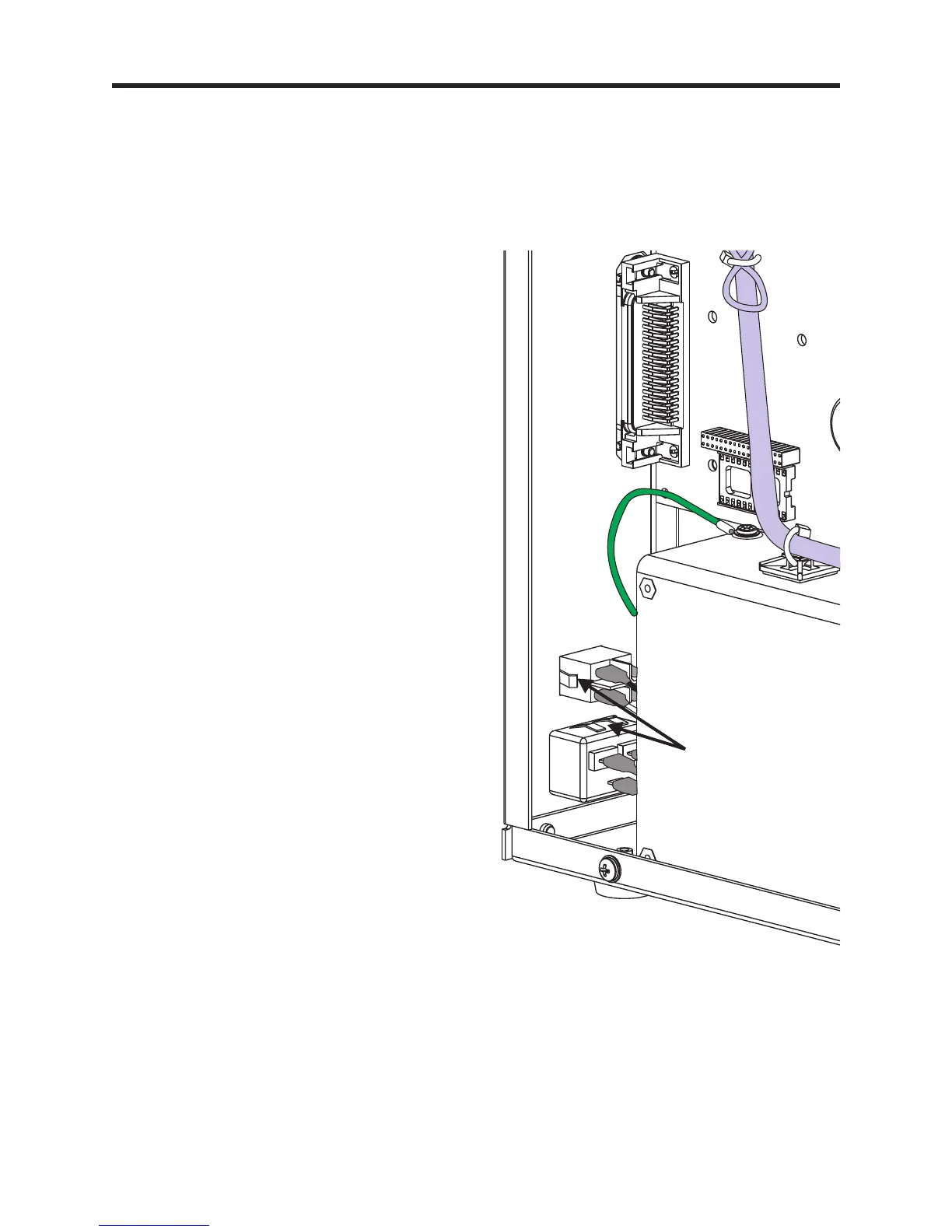
Power Switch Removal
1. Push the retaining tabs into the side of the
power switch or AC power filter module
and slide it out of the back panel.
Power Switch Installation
1. Disconnect the old switch's wires, one at a
time, and reconnect them to the new switch
in the same position. Note the switch's
orientation, 1 (one) to the outside and 0
(zero) towards the center panel.
2. Push the new switch into the back panel
until flush with the back panel. Wiggle it
from the inside to very that it has locked in
place.
AC Power Inlet Removal
1. Push the retaining tabs into the side of the
AC power inlet module and slide the
module out of the back panel.
AC Module Installation
1. Disconnect the old module's wires, one at a
time, and reconnect them to the new switch
in the same position. Note the module's
orientation, ground towards the bottom
plate.
2. Push the new module into the back panel
until flush with the back panel. Wiggle it
from the inside to very that it has locked in
place.
Switch and AC
Power Inlet Module
Retaining Tabs
 Loading...
