Cable Clearance Check Procedure
The printer cables and connectors must not interfere (touch) with any
moving components (belts, gears or springs).
Placement of cable tie points, tie anchors, and cable tension and slack areas are outlined in the
following steps:
980428-109 Rev. 1 Prelim. 25
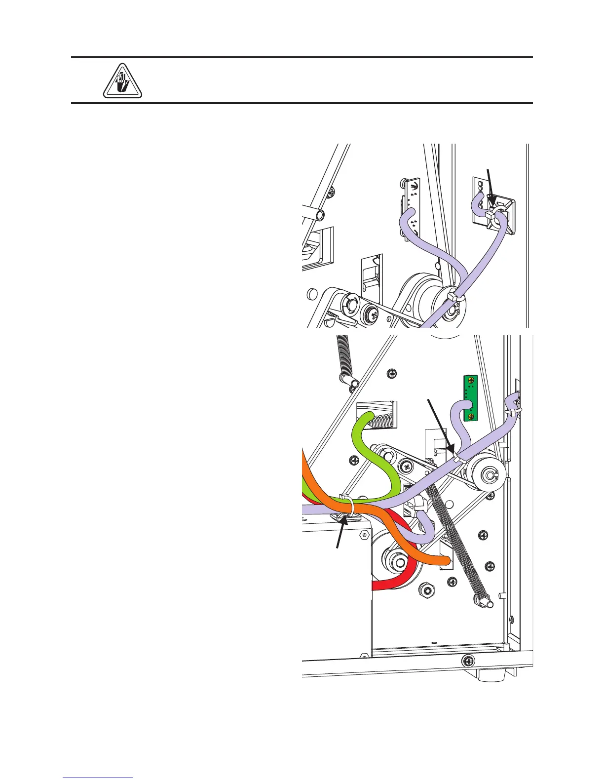
Control Panel Tie Point
1. Pull the control panel cable until minimum
1/4" service loop (slack) is present between
the cable tie and control panel PCBA.
Tighten the tie and cut off the excess.
Cable Tie
Front Power Supply Cable Tie Point
1. Loosely tie the DC power, control panel,
head-up, label sensor, and motor cables
with a cable tie through the front anchor tie
on top of the power supply.
2. Push the label sensor slide to the maximum
distance into the user side of the printer. Pull
the sensor cables through the power supply
anchor tie towards the main PCBA, taught
but not strained. Tighten the tie.
3. Pull the control panel cable through the
power supply anchor tie towards the main
PCBA, taught but not strained.
4. While holding the head-up cable one-half
inch parallel to the center panel of the
head-up PCBA, connect the head-up cable
to the control panel cable with a cable tie.
Pull the head-up cable taught to the power
supply’s front cable anchor tie.
Cable Tie
Front
Anchor Tie
 Loading...
