Assembly
1. Plug the wire bundles, ribbon cables and
ground wire into their connectors on the
board.
2. Align the protective separator # ("fish
paper") against the bottom frame.
3. Align the board onto its post ! and
standoffs ".
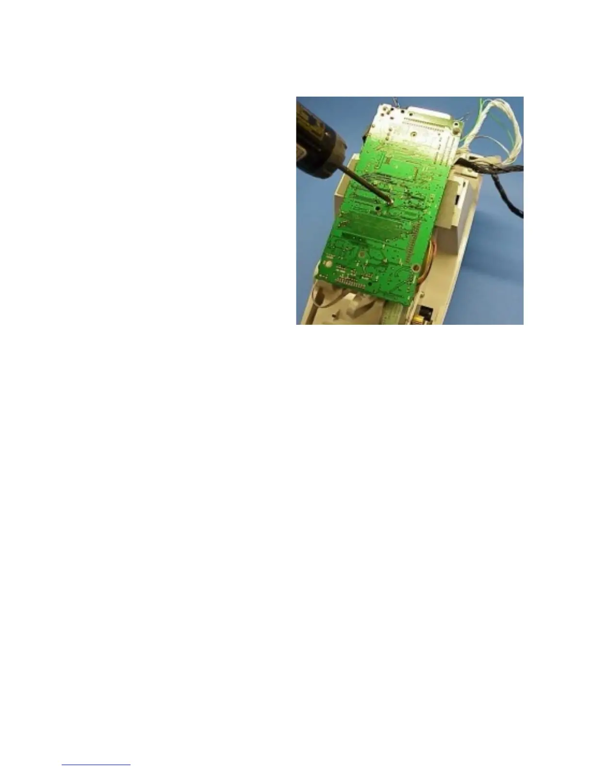
4. On TLP models, replace the screw that
holds the board and use a #1 Phillips
driver to tighten it.
5. Replace the ferrite core around the print
head wire bundles.
6. Provide a loop in the wire bundles and
ribbon cables and secure to the bottom
frame with a tie wrap. Cut off the excess.
Assembling the Printer
Perform the assembly steps of the Bottom Case Replacement (980358-305) procedure.
Reload media. Plug in the power cord, turn on the printer, load media, and run the AutoSense
routine to get a dump mode printout.
980358-001 Rev. B 59