Ribbon Motion Sensor Replacement - TLP 980358-517A
Preparation
Perform the removal steps of the Bottom Case (980358-305), Main PCBA (980358-309), Hinge
(980358-513), Upper Case (980358-514), and Ribbon Carriage (980358-515) procedures.
Removal
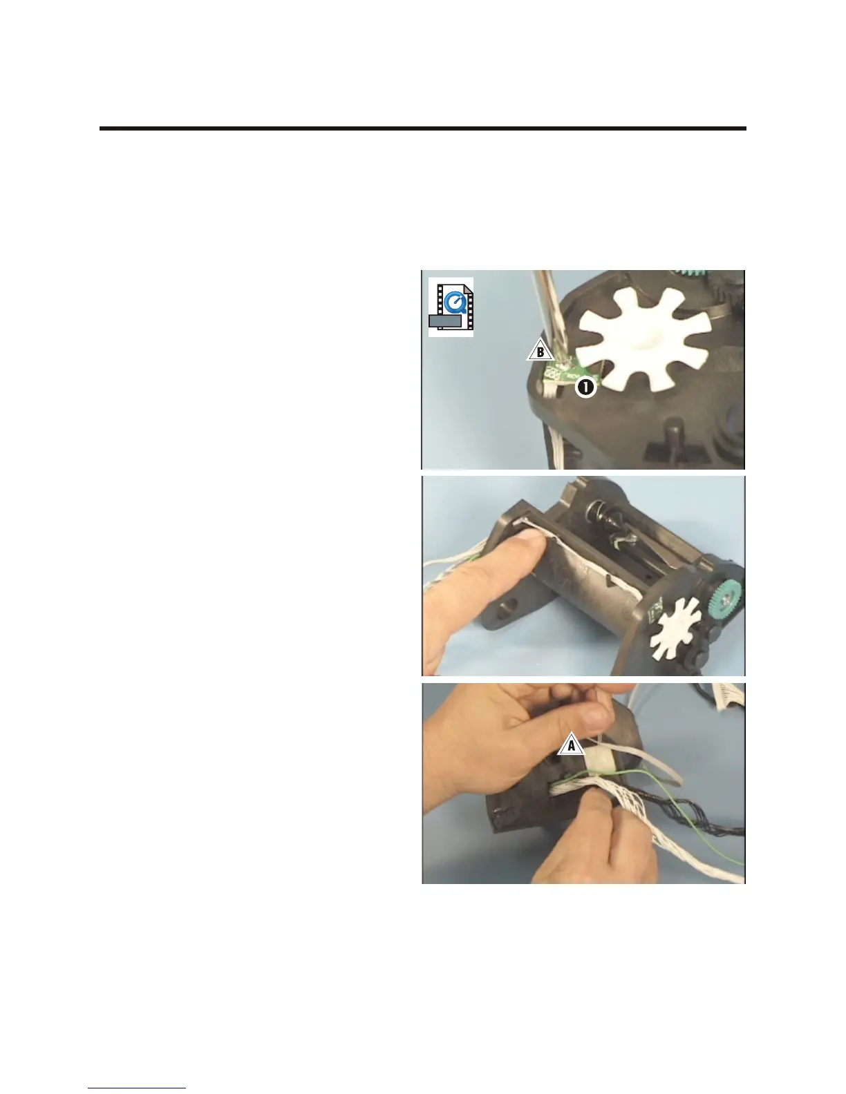
1. On the ribbon carriage, cut the tie wrap !
that holds the wire bundles and ribbon
cables to the right side frame.
2. Use a #1 Phillips driver to loosen the screw
" that holds the sensor 1 to the outside of
the left side frame.
3. Pull the sensor away from the carriage and
pull the wires through both side frames.
Assembly
1. Insert the connector through the outside of
the left side frame.
2. Insert the connector through the inside of
the right side frame.
3. Pull the wires through, and route them
through their guides.
4. Align the sensor so that the wires go to the
rear of the carriage.
5. Replace the screw that holds the sensor to
the left side frame and use a #1 Phillips
driver to tighten it.
6. Secure the wire bundles and ribbon cables
against the carriage with a tie wrap inserted
through the right side frame.
Assembling the Printer
Perform the assembly steps of the Ribbon Carriage (980358-515), Upper Case (980358-514),
Hinge (980358-513), Main PCBA (980358-309), and Bottom Case (980358-305) procedures.
980358-001 Rev. B 79