LSM 710 and LSM 780 NOTES ON DEVICE SAFETY
Systems Power Requirements Carl Zeiss
02/2010 M60-1-0025 e 7
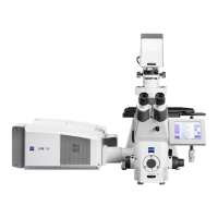
The door interlock interface (Fig. 4/1) is covered
with a green plug to bypass a door interlock.
• To use the interface remove the top of the
green plug and the bypass wire.
• Then connect the wires of the door interlock at
the same position.
Two door interlocks can be connected.
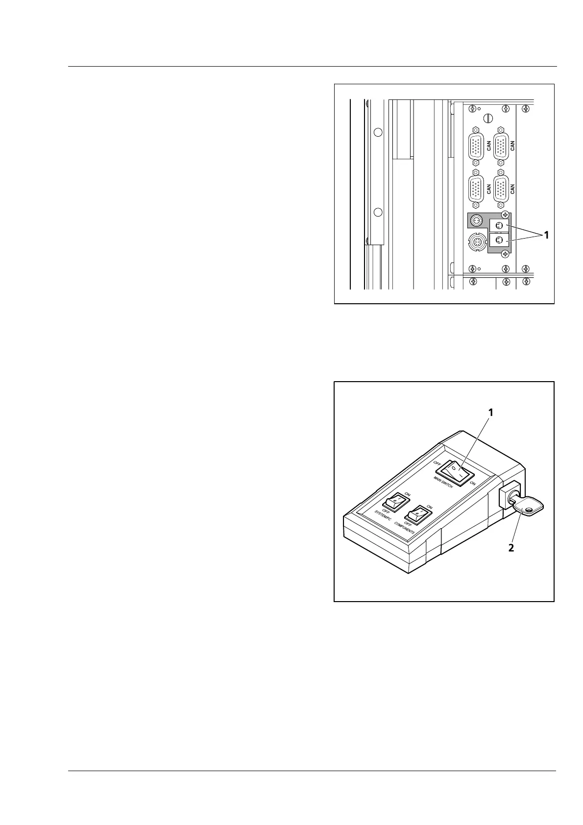
The LSM 710 and LSM 780 systems are controlled
by a remote control. This remote control contains
the main switch for the system
and the key switch
for the laser.
• To start the system switch the main switch
(
Fig. 5/1) to ON.
• To activate the laser turn the key switch
(
Fig. 5/2) to ON position.
Fig. 4 Door interlock interface (1) on the
back of the electronic rack (see
Fig. 2 and Fig. 3, top)
1 Main switch ON/OFF
2 Laser key switch
Fig. 5 Remote control of LSM 710,
LSM 780 systems
 Loading...