Do you have a question about the Zeiss VISUPHOR 500 and is the answer not in the manual?
Details the purpose and how to access the user manual and related documentation.
Provides contact information for user inquiries and feedback regarding the manual or product.
Defines safety symbols and other icons used throughout the user manual for clarity.
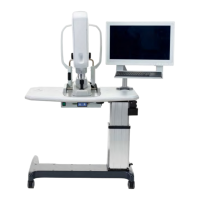
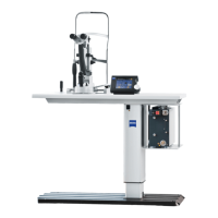
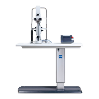
Lists all items included in the basic device package, including the phoropter head and junction box.
Details various assembly adapters and corresponding mounting sets for installing the device.
Covers device classification, manufacturer's declarations, and regulatory compliance statements.
Defines intended use, patient demographics, side effects, contraindications, and user qualifications.
Details reporting requirements for serious incidents and procedures for product disposal within the EU.
Introduces the external labels on the VISUPHOR 500, showing their location.
Explains specific labels (items 1-8) related to manufacturer, identification, and compliance.
Explains additional device labels (items 9-14), including country of origin and medical device markings.
Shows and explains the warning and information labels located on the junction box unit.
Details labels related to CE marking, Bluetooth, FCC/IC registration, and country of origin.
Explains approval labels for specific regions, such as Brazil.
Explains the core functionality of the VISUPHOR 500 digital phoropter and its role in subjective refraction.
Lists the key features and functions offered by the VISUPHOR 500, such as lens setup and pupil distance adjustment.
Provides information on the expected service life of the device and responsibilities for its maintenance.
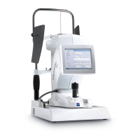
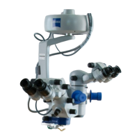
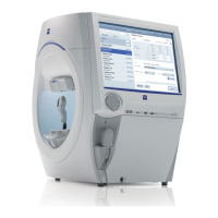
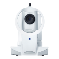
Details the control and functional elements of the VISUPHOR 500 phoropter head unit.
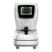
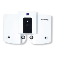
Identifies and explains the control and functional elements on the VISUPHOR 500 junction box.
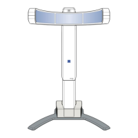
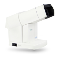
Illustrates and explains the functional elements of the near-point chart used with the VISUPHOR 500.
Provides essential notes on installation, general hazards, and risk of electric shock during setup.
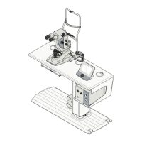
Details the process for safely unpacking and installing the VISUPHOR 500 device.
Details interface dimensions and procedures for mounting the phoropter head using various assembly adapters.
Explains how to connect external devices like lensmeters and autorefractometers to the junction box.
Describes the wireless Bluetooth interface for connecting to the VISUSCREEN control unit.
Outlines essential daily inspections and safety checks required before operating the device.
Provides instructions and warnings for safely powering on the VISUPHOR 500 and VISUSCREEN units.
Covers device preparation steps like leveling, cleaning, and using the near-point chart for examinations.
Explains how to select and display different optotype cards using the near-point chart.
Details transferring objective refraction data and correctly positioning the patient for examination.
Guides on positioning the patient comfortably and adjusting corneal vertex distance (CVD).
Describes the final steps and considerations for conducting the subjective refraction examination.
Provides procedures and safety warnings for properly shutting down and disconnecting the device.
Lists common problems, their possible causes, and corrective measures for the VISUPHOR 500.
Details the procedure for removing and replacing the forehead rest on the phoropter head.
Explains how to remove and insert the face rests for the phoropter head.
Provides instructions and safety warnings for replacing fuses in the power input module.
Offers guidelines for safe cleaning procedures, including warnings about disinfectants and cleaning agents.
Describes how to clean the external housing and glass surfaces of the device.
Details periodic safety checks, including protective earth conductor resistance and leakage current measurements.
Outlines general steps and precautions to follow before replacing any device component.
Describes the disassembly steps for removing the phoropter head, including covers and screws.
Details the disassembly and mounting procedures for replacing the junction box unit.
Advises using only manufacturer-approved accessories and spare parts for safe operation.
Lists physical dimensions, weight, and electrical parameters like voltage, frequency, and power consumption.
Covers device type, protection class, ingress rating, and environmental operating/storage conditions.
Provides technical specifications for lens settings, ranges, and special optical components.
Lists technical details for the high-frequency transmitter, including frequency range and power.
Defines EMC requirements, intended use environments, and limitations on performance due to interference.
Highlights precautions regarding electromagnetic radiation and placement near other equipment.
Details the emission standards (CISPR 11, IEC 61000-3-2) the device complies with.
Lists the immunity standards (IEC 61000-4 series) the device meets for various electromagnetic phenomena.
Provides a list of abbreviations used in the document for quick reference.
Defines technical terms and jargon used within the user manual.
| Display | LCD |
|---|---|
| Sphere Range | -20.00 to +20.00 D |
| Magnification | 1.0x |
| Illumination | LED |
| Type | Phoropter |
| Connectivity | USB |
| Cylinder Axis | 0° to 180° |
| Cross Cylinder | ±0.25D, ±0.50D |
| Convergence | 0 to 10° |
| Auxiliary Lenses | Included |
| Power Supply | 100-240 V, 50/60 Hz |
| PD Adjustment | 48 to 80 mm |