19
With combined heat and cooling
measuring or only cooling measuring
the calculator has to be mounted on
the wall for protection of external
condensation (for Germany and
Austria: in the case of cooling and
combined heat / cooling meters, the
cooling registers are not calibrated
and may not be used for billing pur-
poses in commercial transactions.
For this purpose, devices with a
separate type-examination certicate
are currently required).
The revision of the approval can be
identied clearly in the display menu
(Level 3). The measuring capsule
ow sensor CMF is only allowed to be
used with the connection interface
according to DIN EN 14154-2 respec-
tively DIN EN ISO 4064-4 which are
specied in the technical data. The
use of transition pieces or adapters
inserts is not permitted.
Installation ow sensor (FS)
■
Mount ball valves up- and down-
stream of the ow sensor.
■
Consider the correct installa-
tion point. Normally this is the
return (the colder pipe in heating
systems). Note the type plate
information.
■
Consider the correct ow direc-
tion. This is indicated by an arrow
on the side of the the connection
interface.
■
At type A1, the arrow is at the bot-
tom of the measuring capsule.
■
The use of ow direction convert-
ers is not permitted!
■
Install horizontally or vertically
only, not tilted, inclined or over-
head. Installation into horizontal
or upstreaming or downstreaming
pipelines.
■
Do not install at highest point of
piping to avoid air inside the ow
sensor.
■
Consider the dimensions of
the heat meter. Axial distance
between two ow sensors at least
135 mm.
Installation of the ball valve
■
Mount ball valves up- and down-
stream of the ow sensor.
■
Mount a ball valve with bore
M10x1 for direct sensors in the
supply. This is required for the in-
stallation of the supply sensor (for
type A1 a special ball valve with
temperature sensor connection
is required with external thread
M12x1,5.)
■
For symmetrical temperature sen-
sor installation, mount an identi-
cal ball valve in the return. This is
required for the installation of the
supply sensor.
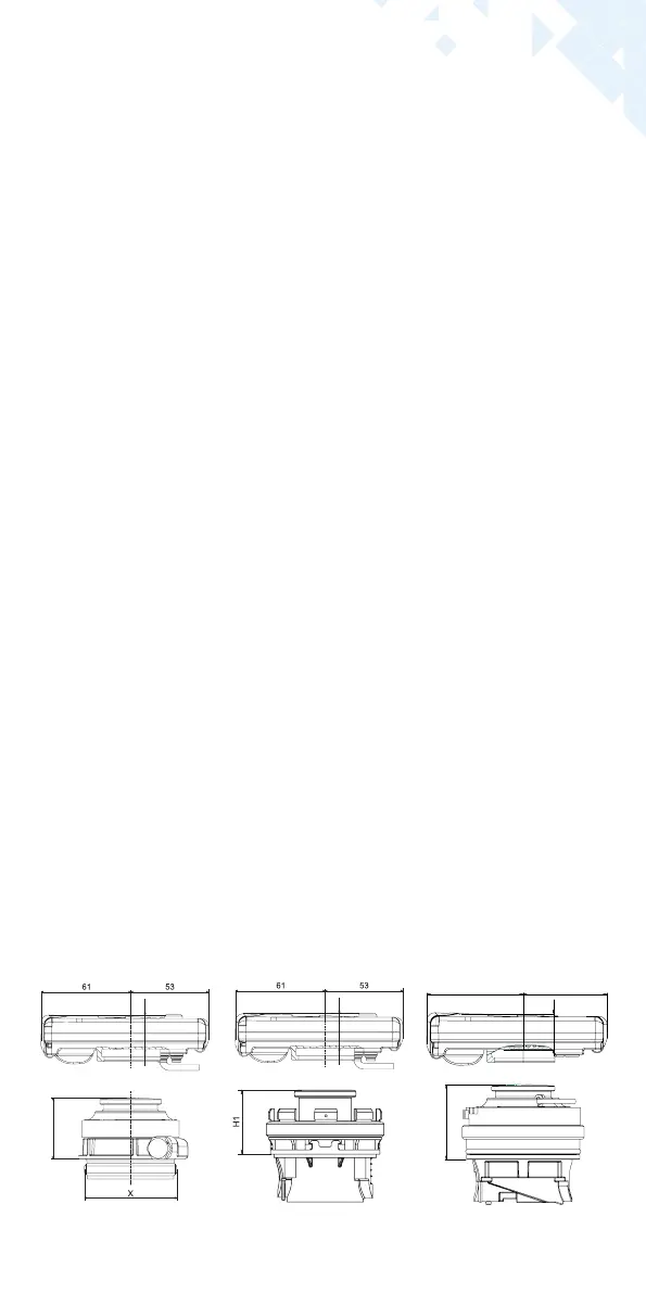
H2=25mm
H2=25mm
H1
H2
H2=25mm
Combi version type IST, TE1,
M60, PCC
Combi version type ASF A1 Combi version type A1
 Loading...