SET UP
Page5-24
5-6.5.1.6 Function Code
L5
– Troll Pulse Duration
This Function determines the length of time that the
Value selected in Function Code
L6
is applied.
The available Values for this Function are
00.0
to
09.9
seconds.
The default Value is
00.6
seconds.
To determine, and if required, change the Value
(Refer to Sections 5-2 and 5-3, page 5-5):
A) With Troll selected, place the Control Head
lever into the Ahead detent.
• If the vessel lunges forward or the shaft takes
too long to start rotating, continue with the next
step.
B) Scroll to Function Code
L5
.
C) Activate Set Up Mode.
D) Scroll Up or Down to the desired Value.
E) Store the Value to memory.
5-6.5.2 Troll Servo Functions
This section along with Section 5-6.4.1, page 5-29, Basic
Tr ol l Command Fun c tions all ows the adjustment of Tr oll
Servo related items:
5-6.5.2.1 Function Code
L1
– Troll Servo Direction
This Function Code determines whether the Troll
Push-Pull c ab le is fully ext ended or ret rac ted whe n a t
Lock-up.
The available Values are:
20
Lock-up – Push-Pull cable fully retracted. (Default
Value)
21
Lock-up – Push-Pull cable fully extended.
To determine, and if required, change the Value
(Refer to Sections 5-2 and 5-3, page 5-5):
NOTE: A
LL
T
ROLL
F
UNCTIONS
OT HER
THAN
L0
WILL
NOT
BE
DISPLAYED
ON
THE
P
ROCESSOR
D
ISPLAY
LED
IF
F
UNCTION
L0
IS
SET
TO
00
. T
O
UTILIZED
T
ROLL
AND
DISPLAY
THE
REST
OF
THE
T
ROLL
F
UNCTIONS
,
A
VALUE
OTHER
THAN
00
NEEDS
TO
BE
ENTERED
FOR
F
UNCTION
L0
.
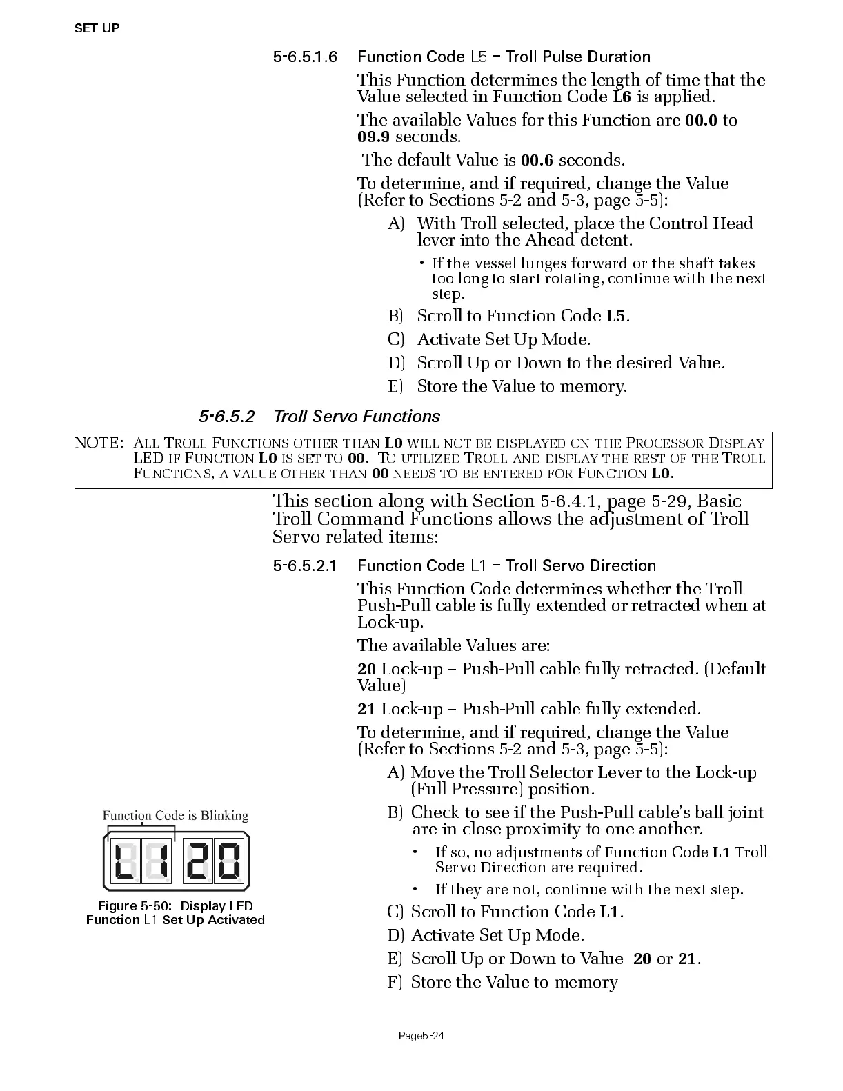
Figure 5-50: Display LED
Function
L1
Set Up Activat ed
A) Move the Troll Selector Lever to the Lock-up
(Full Pressure) position.
B) Check to see if the Push-Pull cable’s ball joint
are in close proximity to one another.
• If so, no adjustment s of F u nc t i on Code
L1
Troll
Servo Direction are required.
• If they are not, continue with the next step.
C) Scroll to Function Code
L1
.
D) Acti v ate Set Up Mode.
E) Scroll Up or Down to Value
20
or
21
.
F) Store the Value to memory

 Loading...