SET UP
Page5-1
5
SET UP PROCEDURE
The Processor utilizes push buttons in conjunction with Display
LED’s to program, adjust, calibrate and set up the various features.
The push buttons also allow you to access and display information
reg ardi n g the h eal th of the Sys tem. Th e f ol l o w i ng paragraph s
explain how to locate and use the push buttons and Display LEDs:
5-1 P
ROCESSOR
C
OMPONENTS
U
SED
I
N
S
ET
U
P
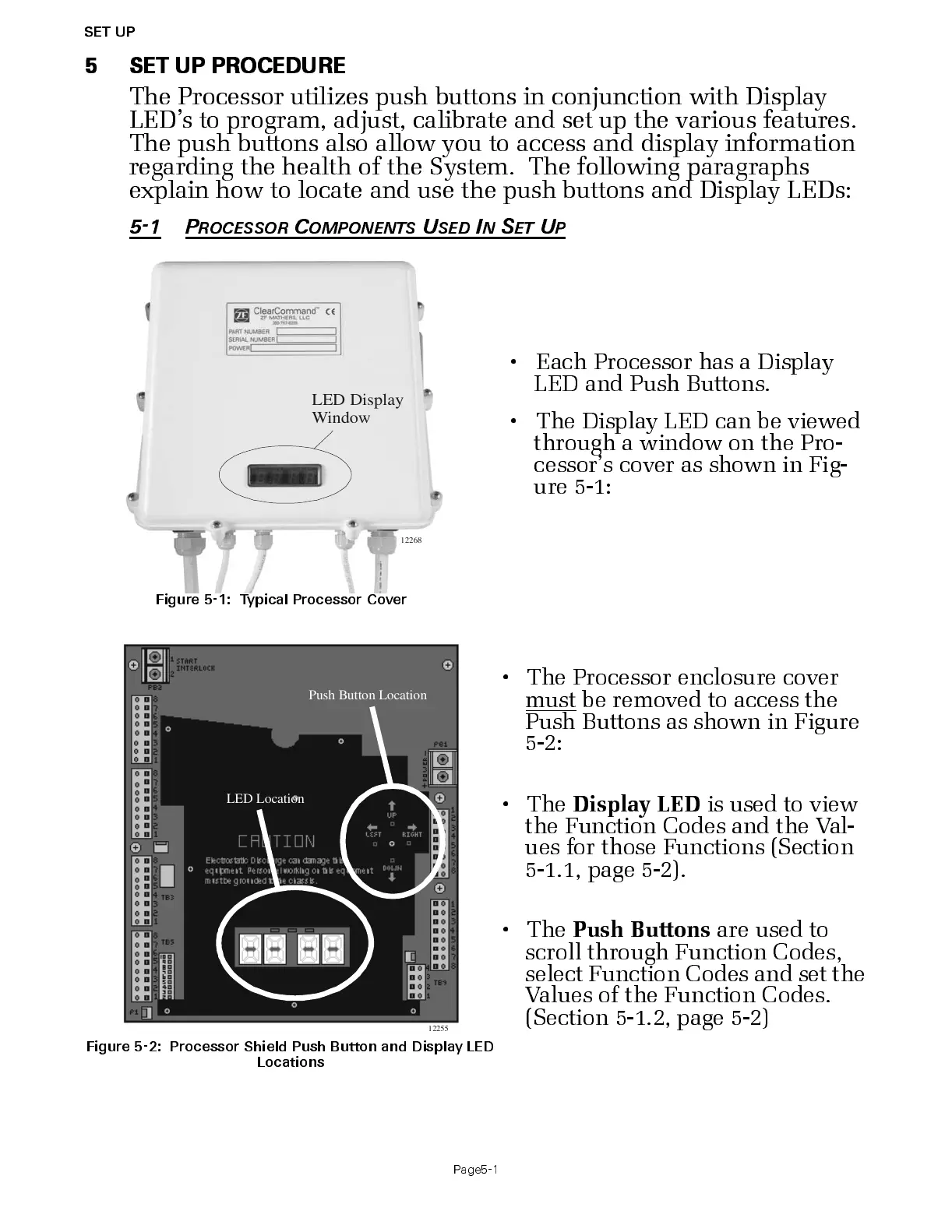
Figure 5-1: Typical Processor Cover
• Each P rocess or has a Dis p la y
LED and Push B uttons.
• The Display LED can be viewed
through a window on the Pro-
cessor’s cover as shown in Fig-
ure 5-1:
Figure 5-2: Processor Shiel d Push Button and Display LED
Locations
• The Processor enclosure cover
must
be removed to access the
Push Buttons as shown in Figure
5-2:
•The
Displa y LED
is used to view
the Function Codes and the Val-
ues for thos e Functions (S ection
5-1.1, page 5-2).
•The
Push Buttons
are used t o
scroll through Func tion Codes,
select Function Codes and s et the
Values of the Function Codes.
(Section 5-1.2, page 5-2)
LED Display
Window
2268

 Loading...