eZ80
®
CPU
User Manual
UM007714-0908 Registers and Bit Flags
12
eZ80
®
CPU Registers in ADL Mode
In ADL mode, the BC, DE, HL, IX and IY registers are 24 bits long for multibyte opera-
tions and indirect addressing. The most significant bytes (MSBs) of these 3 multibyte reg-
isters are designated with a U to indicate the upper byte. For example, the upper byte of
multibyte register BC is designated BCU. Thus, the 24-bit BC register in ADL mode is
composed of the three 8-bit registers {BCU, B, C}. Likewise, the upper byte of the IX reg-
ister is designated IXU. The 24-bit IX register in ADL mode is composed of the three 8-bit
registers {IXU, IXH, IXL}.
None of the upper bytes (BCU, DEU, IXU, etc.) are individually accessible as standalone
8-bit registers.
MBASE is not used for address generation in ADL mode; however, it can only be written
in ADL mode. The Program Counter is 24 bits long, as is SPL. IEF1, IEF2, ADL, and
MADL are single bit flags.
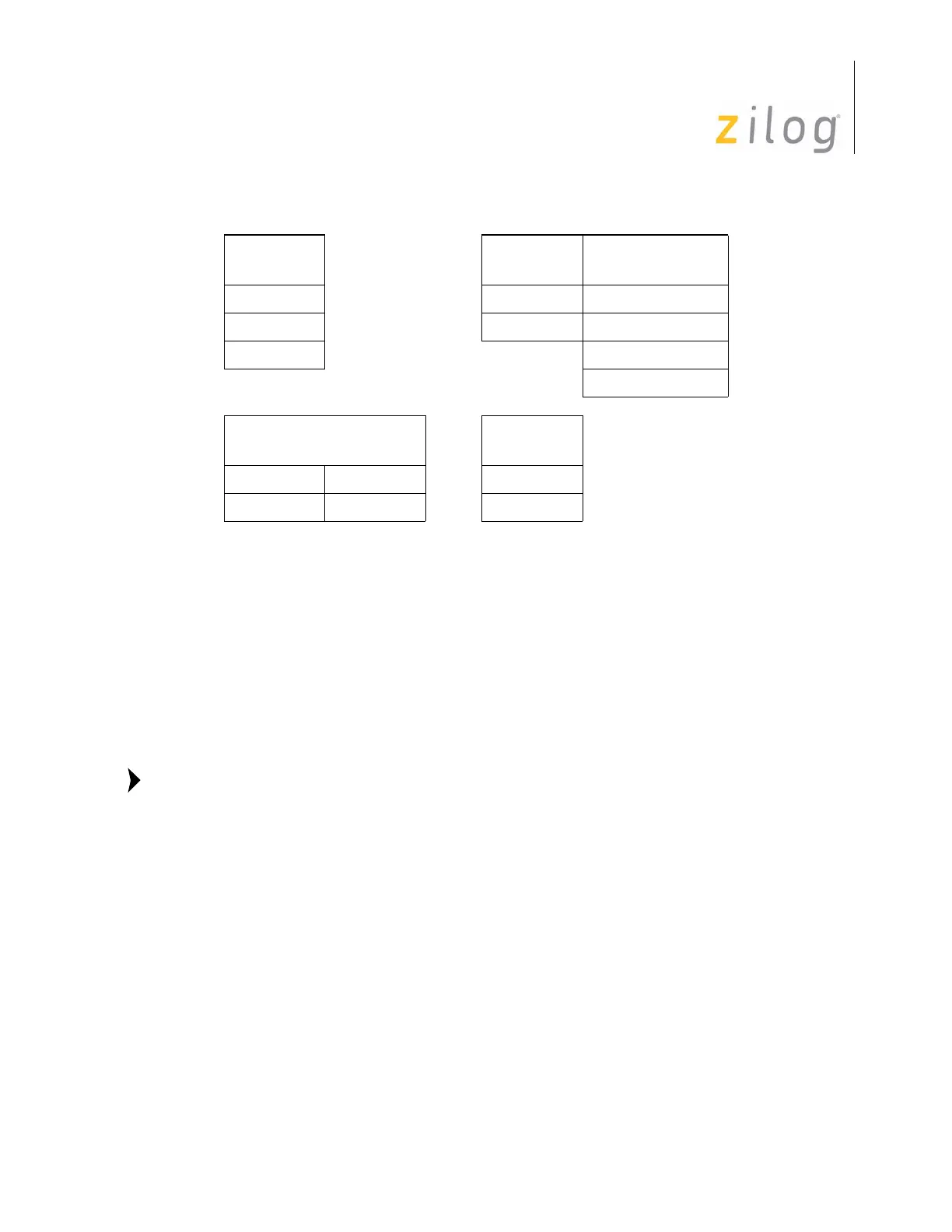
The CPU registers and bit flags during Z80 mode operation are indicated in Tables 3 and
4. Reset states are detailed in Table 5.
Table 2. CPU Control Registers and Bit Flags in Z80 Mode
8-Bit
Registers
16-Bit
Registers Single-Bit Flags
I SPS ADL
MBASE PC MADL
RIEF1
IEF2
Individual 8-Bit Registers
Or
16-Bit
Registers
IXH IXL IX
IYH IYL IY
 Loading...