Page 6 of 24 804545 03.17 1.00
3.3 Electrical
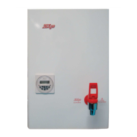
Warning: Do not turn on the power until instructed. Water must first
be available from the tap outlet to prevent damage.
For an exposed electrical connection, the pre-fitted flex and plug cable
is plugged into the PCB as shown. Use a standard GPO power outlet
within 1500 mm from the heater with adequate power for the unit.
For a concealed electrical connection, disconnect the pre-fitted
flex and plug cable at the PCB connector and discard. Connect the
concealed power cable through the rear access opening to the green
terminal block on the PCB.
Check that the earth is connected through the PCB to the chassis with
an ohm meter.
Warning: Do not connect both options. It is essential that the flex and
plug cable is removed from the PCB if the concealed connection is
used. Otherwise the GPO plug will become live.
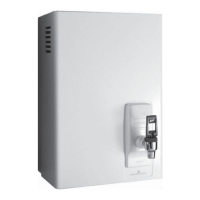
Step 4 – Installing Filter Guide
Assemble the fi lter guide provided with the unit, make sure it is locked in position, then put the cover back on.
1. Push the fi lter guide upwards
2. Rotate clockwise until
locked
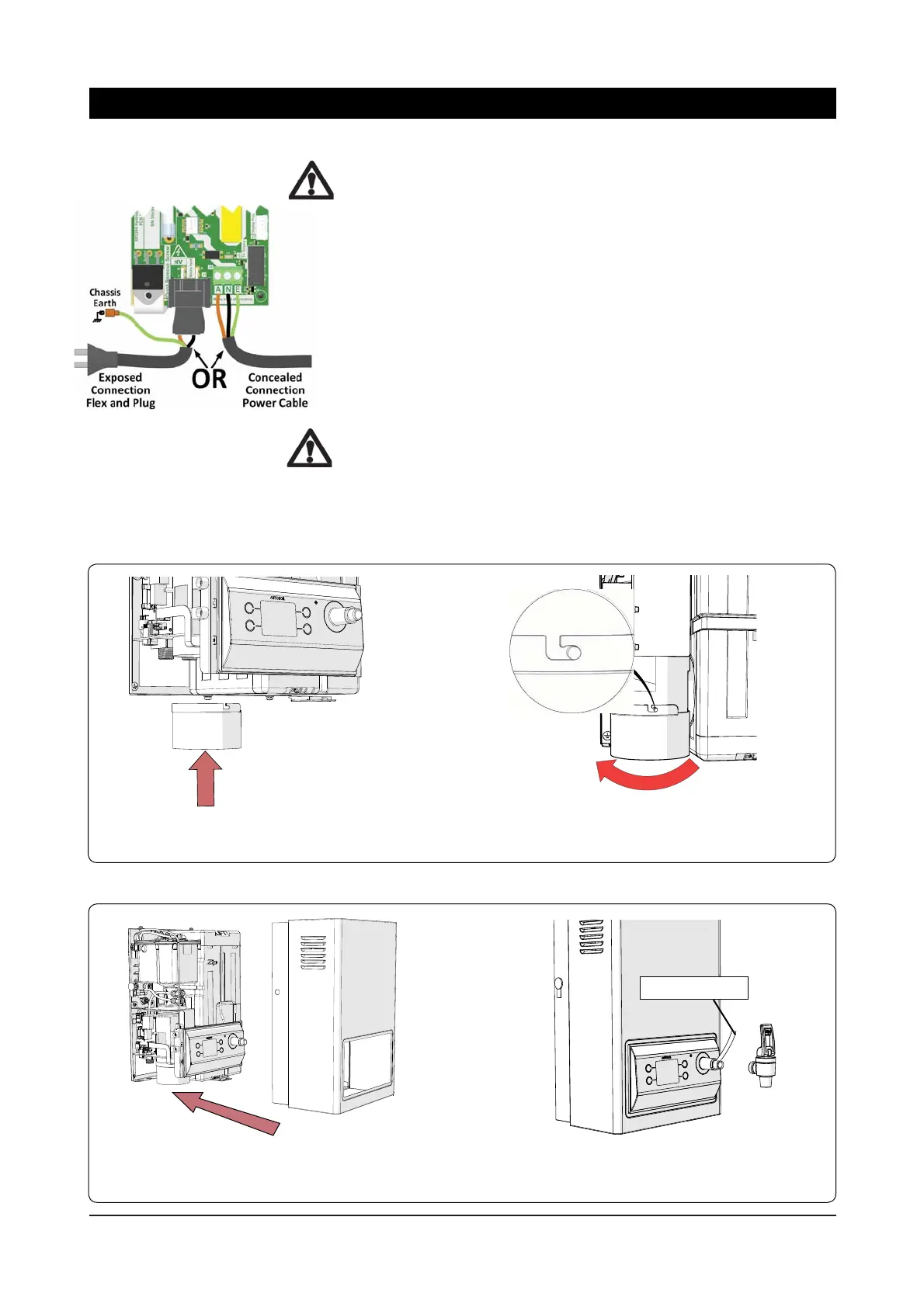
Thread Tape
2. Before installing the tap, ensure suffi -
cient thread tape is applied to the thread.
1. After the fi lter guide is installed, fi t the
cover to the unit and fi x with screws top and
bottom.
Step 5 – Installing Tap
Installation Procedures