22 807042 v1.02 08.22 HydroTap G5 UltraCare Install Instructions
UV-C Module
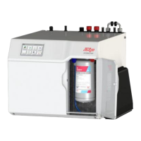
SECTION 13: Connect the Command Centre
• Connect chilled water hose to UV-C
module.
Push hose at least 15mm over the fittings.
• Ensure that the hose has a constant fall.
• Insert UV-C module into the port marked
CHILLED OUT.
• Plug USB cable from UV-C
module into the port at the
side of the Command Centre.
• The USB cable can be inserted either
direction (no polarity).
• Plug the 12V UV-C module power
supply into the Command Centre.
• Insert all connectors square on &
firmly in place.
• Do not apply off axis or lateral force to
the connections.
UV-C Power supply & bracket
Self adhesive
L-shaped bracket
UV-C
power supply
• Connect the UV-C power supply to the power outlet
• Ensure the self adhesive L-shaped bracket (supplied)
is fitted in position, this will
protect the power supply from
accidental disconnection.
Do not switch on the Command
Centre electricity supply until
commissioning the system
Chilled water
hose
UV-C
module
Use only the power supply provided
 Loading...