CEX-O_CEX-U, Maintenance and User Instructions V1.02 Page 8 March / 2014
Electrical connection
The electrical installation including earthing and cross
bonding should comply with current IEE regulations and
any Local Authority requirements.
The appliance must be installed according to the
specication on the rating plate and the technical
specications.
The appliance must be earthed.
The appliance must be permanently connected to the
electrical supply through an isolation switch having a
contact separation of at least 3mm on all poles.
The cross sectional area of the connection cable
must be in accordance with the power rating of the
appliance and the specic requirements of the
installation site up to a maximum cable size of 10mm
2
.
Take care to protect the wiring from damage during
installation and ensure that any uninsulated wiring is not
directly accessible after installation.
To protect the appliance, a circuit breaker must be
tted with a rating suitable for the nominal current of
the appliance.
Check that the power supply is switched off prior to
electrical connection!
1. With the appliance cover removed insert the power
cable through the water splash protection grommet
in the backplate. The splash protection grommet
must be used and free from damage.
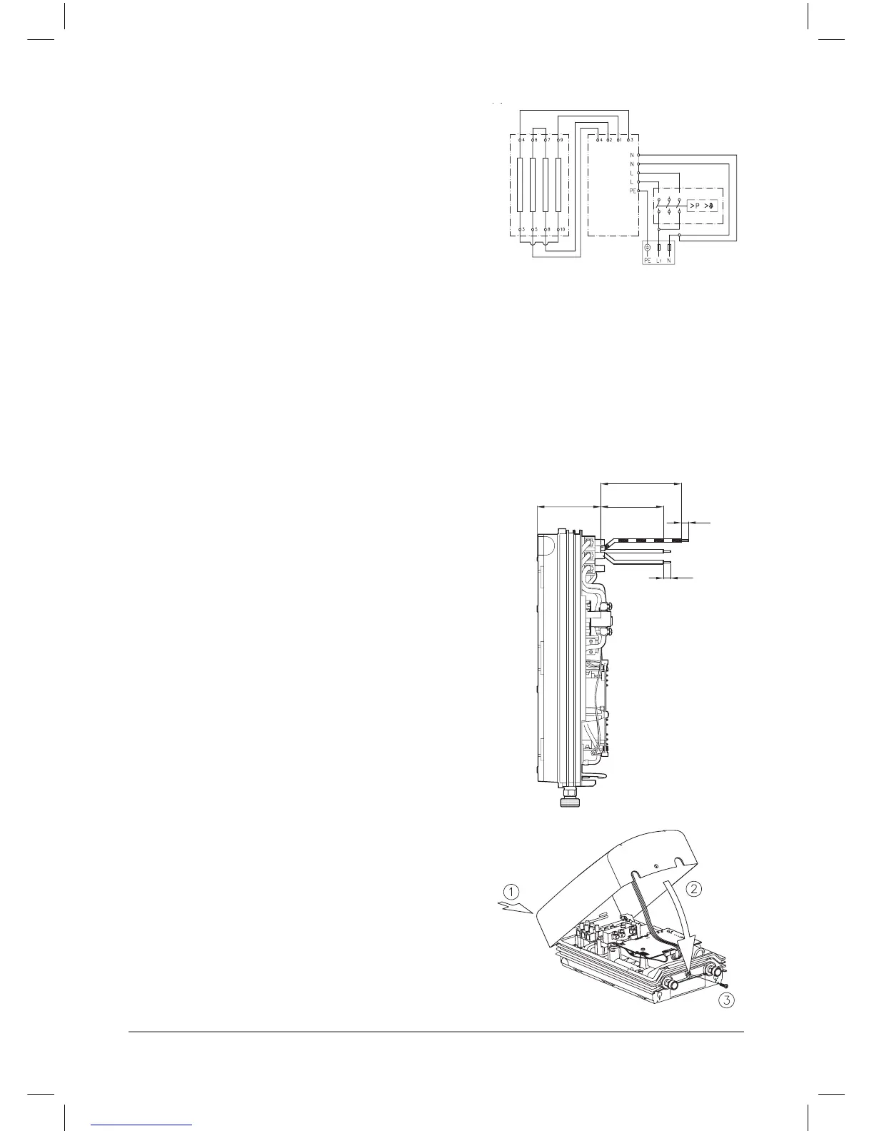
2. Remove inner and outer insulation from the
connecting cable to the lengths shown in Fig 4.
3. Secure the cable using the cord grip. The cord grip
must be used.
4. Fit the connecting cables into the terminal block
according to the wiring diagram above. Ensure all
connections are fully tightened and secure.
5. Re-t the appliance cover taking care not to trap
the cable from the display panel and secure the
cover with the xing screw (see Fig 5).
110
90
8
71~76
8
Wiring Diagram
1. Circuit board
2. Heating element
3. Safety pressure switch and
safety thermal cut-out
4. Terminal block
Fig. 4
Fig. 5
1 3
4
2