F2MUX
FAMILY OF CONVERTER DEVICES TYPE F2MUX 27/28
USER GUIDE - Rev. V00 (June 2021)
5 TEST DEVICES
5.1 INTF2 INTERFACE LOOP
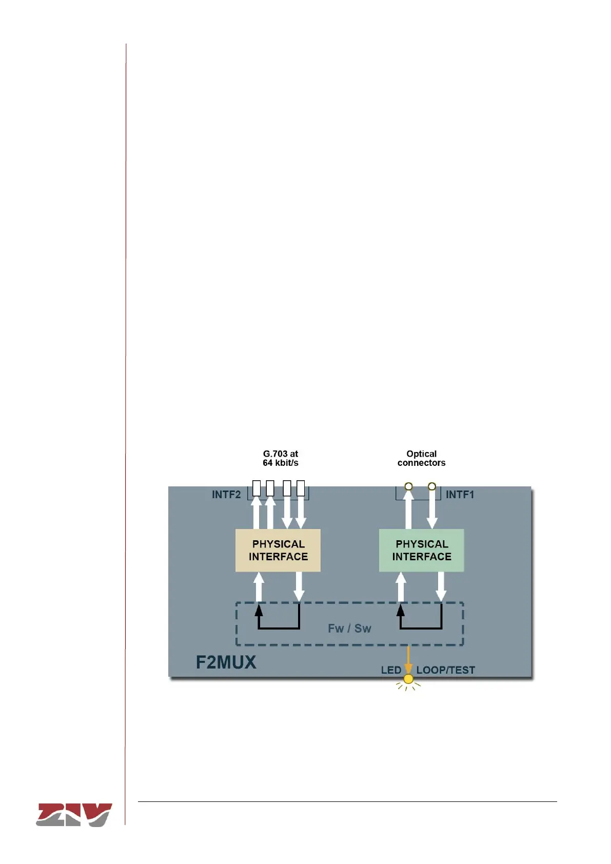
By putting the front-plate switch in LOOP position, a loop is generated. As the example in
FIGURE 15 shows, the loop is established between transmit and receive of the INTF1
interface, and between transmit and receive of the INTF2 interface. In the example, the
INTF2 interface is associated with the F2MUX.#1 version.
The loop allows the communication channel between the F2MUX and the multiplexer
equipment or another telecommunication equipment to be verified.
When the equipment is in loop mode, the LED on the front plate near the loop/test switch
lights up in amber.
FIGURE 15 Loop example in INTF2 interface