http://www.zketech.com
EBC-A10H User Manual
Copyright (C) 2006-2016 ZKETECH
10) Four lines: voltage and current channels separated for high test accuracy
11) LCD display: voltage, current, time, capacity, and etc.
12) PC connection: the tester can connect to a computer through a designated USB-TTL cable
for more functions, like graphs, calibration, firmware upgrade, and test circulation.
3. Connecting patterns
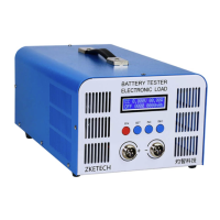
3.1 Testing Ports
The tester has four banana jacks which connect with A+/V+/V-/A-. A+ and A- ports are
connected with the positive and negative ends of the test objects, working as the current
channel in charging and discharging. V+ and V- ports are connected with the positive and
negative ends of the test objects, working as the voltage channel in voltage tests. This way of
using four individual cables will help eliminate the effect of wires on the test result and
improve the test precision.
3.2 PC Connection
The tester can be connected with a computer through a designated USB-TTL cable.
3.3 Input Power:
The tester works on a power supply of DC 12-19V, 4A or above and interface specification of
5.5/2.1 (inside positive and outside negative).
4. Display and setting
4.1 Buttons
4.1 Buttons
SET —— setting knob (rotate to left/right and press)
ON —— start
4.2 Testing interface
The first line shows testing mode, voltage and current. Testing modes include:
² CC – constant current discharging
CP – constant power discharging