9
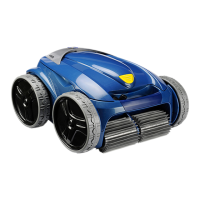
− Thread the strips into their respective slots and pull them very gently so that the heels go through
to the other side of the slots
− With a pair of scissors, cut strips at least 5 mm from the heel (diagram 18).
2.3. ROTOR
a) Disconnect the rotor from the control unit.
b) Holding the flow guide remove the four 2.9 X 9.5 (W0351A) self-tapping screws.
c) Remove the rotor (using a screwdriver as a lever).
d) Remove the flow guide to clear access to the rotor.
e) Refit the rotor.
f) Refit the flow guide and the four screws. (Make sure the rotor isn't touching the flow guide.)
2.4. HANDLE
The handle can be removed from the housing to avoid scratches if you need
to take out the track plates.
To remove the handle, unscrew the two M5X35 and the spreaders.
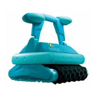
2.5. BUMPER
The bumper needs to be removed before removing the plates.
a) – b) Position a large flat-bladed screwdriver
between the bumper and the housing, using
the brush holder as a lever.
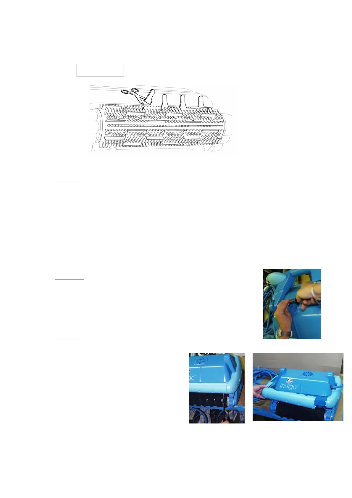
c) Repeat this step in the opposite corner.
d) Remove the 2 halves assembled (1 front, 1
lateral)
a-b d
Diagram 18