1
© Copyright 2017 Zoeller
®
Co. All rights reserved.
INSTALLATION INSTRUCTIONS
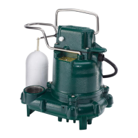
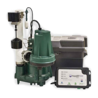
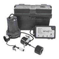
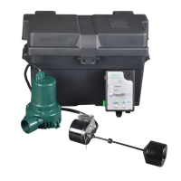
RECOMMENDED MODELS
P/N 006355
Notice to installing contractor: Instructions must remain with installation.
FM0447
Rev. A
0717
Supersedes
1216
PREINSTALLATION CHECKLIST - ALL INSTALLATIONS
DATE INSTALLED:
MODEL NUMBER:
EFFLUENT*/SUMP/DEWATERING SEWAGE
55 / 59, 72, 73, 75, 76, 139 Series 211, 212 Series
140 / 4140, 145 / 4145, 160 / 4160 Series 270 / 4270 Series
180 / 4180, 191, 371, 372, 373 Series 280 / 4280, 290 / 4290 Series
Product information presented
here reects conditions at time
of publication. Consult factory
regarding discrepancies or
inconsistencies.
MAIL TO: P.O. BOX 16347 • Louisville, KY 40256-0347
SHIP TO: 3649 Cane Run Road • Louisville, KY 40211-1961
TEL: (502) 778-2731 • 1 (800) 928-PUMP • FAX: (502) 774-3624
Visit our web site:
www.zoellerpumps.com
Your Peace of Mind is Our Top Priority
®
* Efuent systems should specify that pumps should not handle solids exceeding 3/4” (19 mm) in order to prevent large solids from entering leeching elds, mound systems, etc.
(70 Series have 3/8” (9 mm) solids capability. 50, 140/4140, 371 and 372 Series have 1/2” (13 mm), 130 Series has 5/8" (16 mm), 145/4145, 160/4160, 180/4180 and 373 models
have 3/4” [19 mm].) Where code permits, sewage pumps can be used for efuent systems. Non-automatic pumps with external-level controls are recommended for septic tank
efuent applications.
1. Inspect all materials. Occasionally, products are damaged during shipment. If the unit is damaged, contact your dealer before using. DO NOT remove the test plugs from the pump.
2. Carefullyreadtheliteratureprovidedtofamiliarizeyourselfwithspecicdetailsregardinginstallationanduse.Thesematerialsshouldberetainedfor future reference.
SEE BELOW FOR
LIST OF WARNINGS
SEE BELOW FOR
LIST OF CAUTIONS
REFER TO WARRANTY ON PAGE 2.
1. Toreducetheriskofelectricalshock,aproperlygroundedreceptacleorcontrolbox
must be installed in accordance with the governing codes. Never remove ground
pin from plug.
2.Makecertainthatthegroundfaultinterrupterprotectedreceptacleorcontrolboxis
withinthereachofthepump’spowersupplycord.DONOTUSEANEXTENSION
CORD.Extensioncordsthataretoolongortoolightdonotdeliversufcientvoltage
to the pump motor, and they could present a safety hazard if the insulation were to
become damaged or the connection end were to fall into a damp or wet area.
3.Makesurethepump'selectricalsupplycircuitisequippedwithfusesorcircuitbreakers
of proper capacity. A separate branch circuit is recommended, sized according to the
local electrical codes for the current shown on the pump name plate.
4. Testing for ground.Asasafetymeasure,eachelectricaloutletshouldbecheckedfor
ground using a circuit analyzer which will indicate if the power, neutral and ground wires
arecorrectlyconnectedtoyouroutlet.Iftheyarenot,callaqualiedlicensedelectrician.
5. FORYOURPROTECTION,ALWAYSDISCONNECTPUMPFROMITSPOWER
SOURCEBEFOREHANDLING.Ifpumpiswireddirect,de-energizethecircuitat
thecontrolbox.Wearinsulatedprotectiveshoesanddonotstandinwater.Pumps
equippedwitha3-pronggroundplugaredesignedtohelpprotectagainstelectrical
shock.DONOT,UNDERANYCIRCUMSTANCES,REMOVETHEGROUNDPIN.
6. Installation and servicing of the pump, electrical circuits and hardware should only be
performedbyaqualied,licensedelectrician.
7. Risk of electrical shock. Do not remove power supply cord and strain relief or connect
conduit directly to the pump. If the supply cable is damaged, it must be replaced by
theManufactureroranAuthorizedServiceandWarrantyCentertoavoidahazard.
8. Pumpcontainsoilwhichbecomespressurizedandhotwhenoperating.Allow2-1/2
hours after disconnecting before attempting service.
9. Pumpisnotintendedforpotablewaterduetopossiblecontaminationbyoilcontained
in the pump.
10. Risk of electrical shock.Thesepumpshavenotbeeninvestigatedforuseinswim-
ming pools and marine areas.
11.AccordingtothestateofCalifornia(Prop.65),thisproductcontainschemicals
knowntothestateofCaliforniatocausecancerandbirthdefectsorother
reproductive harm.
1. Checktobesureyourpowersourceiscapableofhandlingthevoltagerequirements
of the motor, as indicated on the pump name plate.
2. Theinstallationofvariableleveloatswitchesistheresponsibilityoftheinstalling
party,andcareshouldbetakenthatthetetheredoatswitchwillnothanguponthe
pump apparatus or pit peculiarities and is secured so that the pump will shut off. It
isrecommendedtouserigidpipeandttingsandthepitbe18"(46cm)orlargerin
diameter.
3. Vent hole.Itisnecessarythatallsubmersiblesump,efuent,andsewagepumps
capableofhandlingvarioussizesofsolidwastebeofthebottomintakedesignto
reducecloggingandsealfailures.Ifacheckvalveisincorporatedintheinstallation,a
3/16"(5mm)ventholemustbedrilledinthedischargepipebelowthecheckvalveand
pitcovertopurgetheunitoftrappedair.Ventholeshouldbecheckedperiodicallyfor
clogging.TheventholeonaHighHeadapplicationmaycausetoomuchturbulence.
If you choose not to drill a vent hole, be sure the pump case and impeller is covered
withliquidbeforeconnectingthepipetothecheckvalve.NOTE:THEHOLEMUST
BEBELOWTHEBASINCOVERANDCLEANEDPERIODICALLY.Waterstreamwill
be visible when pump is operating.
4. Pumpshouldbecheckedfrequentlyfordebrisand/orbuildupwhichmayinterfere
withtheoat“on”or“off”position.Repairandserviceshouldbeperformedbyan
AuthorizedServiceandWarrantyCenter.
5. Maximum operatingtemperatureforstandardmodelpumpsmustnotexceed
130°F(54°C).Maximumoperatingtemperaturesfor70seriesandmodel211
mustnotexceed110°F(43°C).Maximumoperatingtemperaturesfor73,75,
212seriesandmodel211mustnotexceed104°F(40°C).
6. DonotoperateapumpinanapplicationwheretheTotalDynamicHeadislessthan
theminimumTotalDynamicHeadlistedonthePumpPerformanceCurves.
7. Forhealthreasons,donotunplug,turnoff,ordisablepumpandusepumptank
systemasawaytollupasinkorlaundrytray,etc.
8. PumpsmustbeinstalledinaccordancewiththeNationalElectricalCodeandall
applicablelocalcodesandordinances.Pumpsarenottobeinstalledinlocations
classiedashazardousinaccordancewithNationalElectricCode,ANSI,NFPA70.
NOTE:Pumpswiththe"UL"markandpumpswiththe"US"markaretestedtoULstandard
UL778.CSAcertiedpumpsarecertiedtoCSAstandardC22.2No.108.
Register your
Zoeller Pump Company
Product on our website:
http://reg.zoellerpumps.com/
NOTICE: VENT HOLE FOR
CHECK VALVE
SEE #3 IN CAUTION SECTION
BELOW AND #4 ON PAGE 3
Many Zoeller products contain
registeredtrademarksfor
designand/orthecolorgreen:
U.S.#4,849,524/#5,024,907