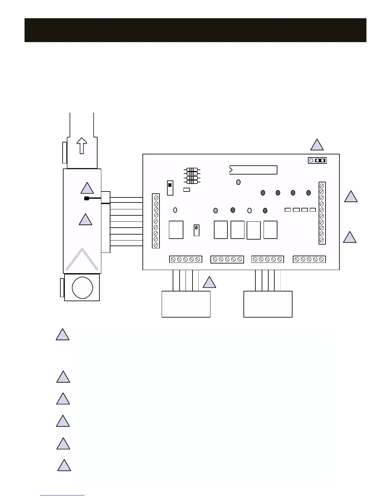
WIRING – GAS/ELECTRIC DTGE4-2
HVAC unit and LAS terminals. Do not connect Y2 or W2 for single stage heat/cool systems.
Use minimum 18 gauge for all wiring.
All wiring must meet state and local codes.
Zone damper terminals. Refer to “Wiring – Zone Dampers” section, pg. 5.
1. LAS. Locate the leaving air sensor in the supply air stream, as far from the coil/heat exchanger as possible
before the bypass takeoff. Do not locate the LAS downstream of the bypass takeoff. Ensure wire polarity is
correct. Refer to "CAPACITY CONTROLLER- LAS INSTALLATION" on P. 11 for further information.
NOTE: Shielded conductor provided for installations with spark ignition or distances from controller to LAS
beyond 10’. 18/2 thermostat wire may be used in most applications.
2. Connect W2 and Y2 of the DTGE4-2 only if there are two heat and/or two cool stages.
3. Connect C from the controller to the thermostat 24V AC common terminal if hard wired. Not required
with use of battery operated thermostats. Refer to "THERMOSTATS- COMPATIBILITY" on P. 12 for further
information.
4. Zone damper terminals. Refer to "WIRING- ZONE DAMPERS" on P. 5.
5. Install one 24V AC transformer, sized and fused for the total number of zone dampers. See "DAMPER
TRANSFORMER" on P. 23.
6. Fan cycling jumper: A – FAU fan control; B – electric heat, fan on with heat call
1
1
2
3
4
5
6
2
3
4
5
6
DigiTract 4-2 Gas/Electric 2-Stage Heat/Cool