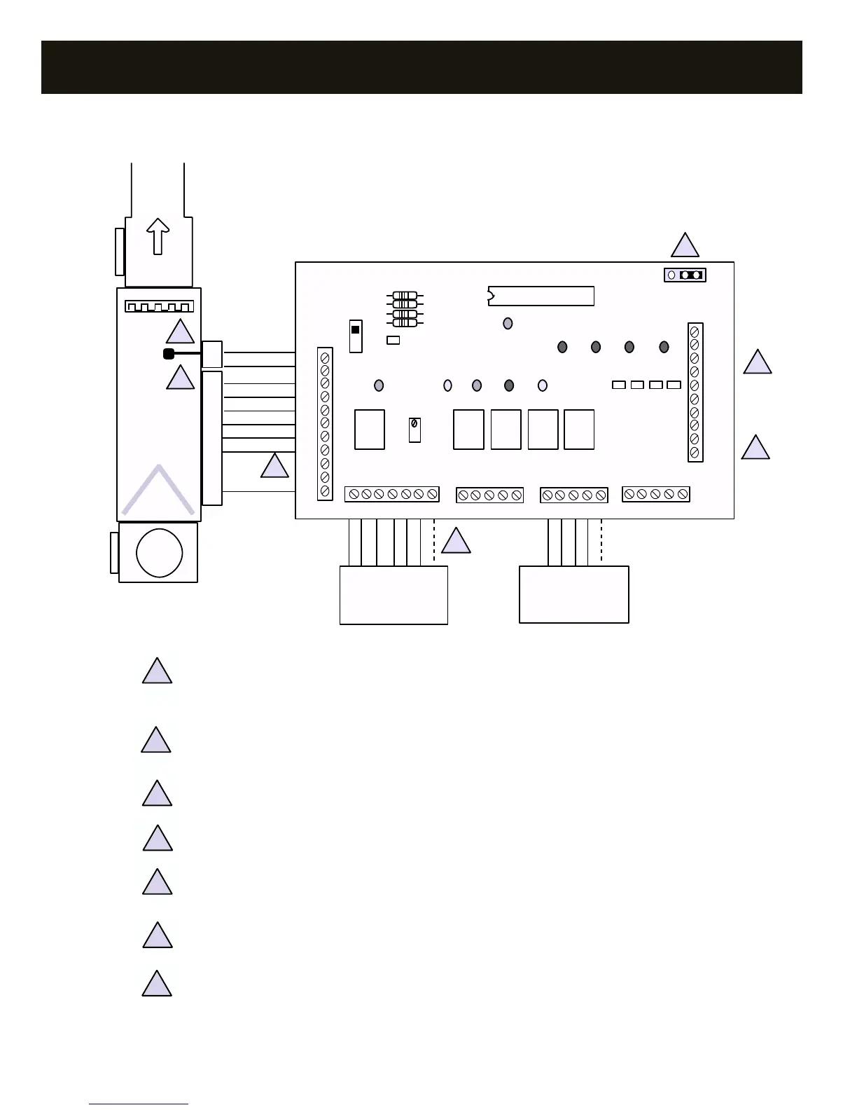
LAS. Locate the leaving air sensor between the refrigerant coil and the electric heat coil(s) or other auxiliary
heat source. Verify that the polarity is correct. Refer to “CAPACITY CONTROLLER – LAS INSTALLATION”
page 11, for further information.
Connect W2 from the controller to the unit’s electric heat stage terminal designation. It is recommended to
install an outdoor thermostat in series with any electric heat stages.
Connect C from the controller to the thermostat 24V AC common terminal if hardwired. Refer to “ZONE
THERMOSTATS – COMPATIBILITY” page 12, for further information.
Zone damper terminals. Refer to “WIRING – ZONE DAMPERS” on page 5.
Install one 24V AC transformer, sized and fused for the total number of zone dampers. See “DAMPER
TRANSFORMER” on page 23.
Emergency heat terminal, E. Use only if emergency heat source is different from auxiliary heat W2. If used,
do not jumper to W2.
Reversing valve jumper: B – energize for heat; O – energize for cool
NOTE: Some combination thermostats do not have an E terminal. Connect W2 of the thermostat to the E ter-
minal of STAT 1 terminal block.
4