1
2
3
3
4
4
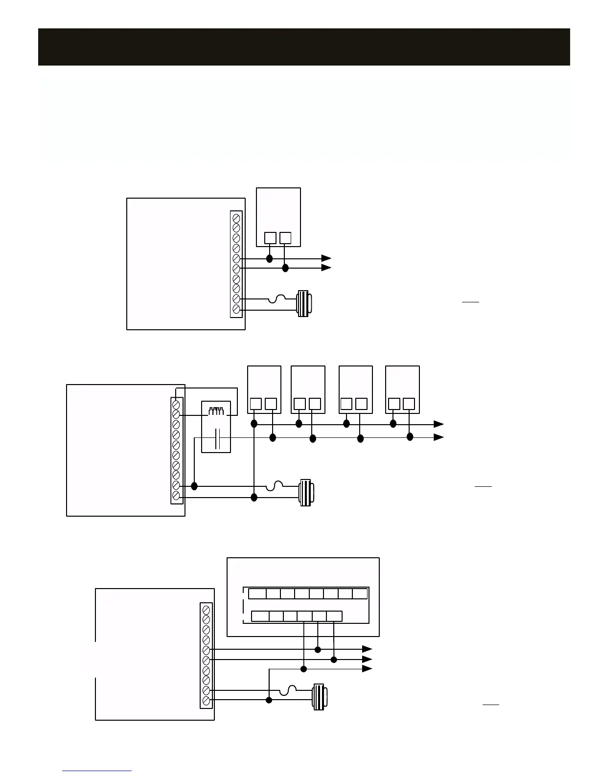
TR1
TR2
2
1
DIGITRACT 4-2
SYSTEM
CONTROLLER
N/C - No connection
*
- Factory wired motor
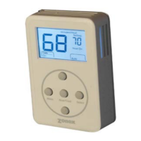
101 series dampers include:
101AMPD, 101MRTD & 101CD
DAMPER RELAY BOARD
RC MCRCWWY RO
TB2
TB1
N/C N/CN/C
N/C N/C N/CN/CN/C
***
101 SERIES DAMPER
TO ADDITIONAL
101 SERIES DAMPERS
IF APPLICABLE
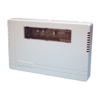
FUSED 24VAC XFMR.
Transformer and fuse must be sized for
total
number of zone dampers. See Transformer/Fuse
Sizing Table on page 23.
GRd BWWY
B must wire to bottom
terminal and Rd must wire
to top terminal. Do not
reverse.
{
{
G must wire to TR2.
Do not wire to TR1.
Method 3: Wiring 101 Series Medium/Heavy Duty Dampers to a Zone
There are three methods of wiring the zone dampers. If necessary, you
can mix wiring methods on different zones to suit your application.
Method 1: If wiring two or three TR series dampers to a zone, wire per
method 1.
Method 2: If wiring more than three TR series dampers to a zone, use
method 2. This method requires a 24V ac, SPNO relay.
Method 3: If using 101 series dampers with a DTGE4 controller, wire
per method 3. Notice: 101 series dampers are required for all systems
over 5 tons. Refer to Parts Selection Table, page 14.