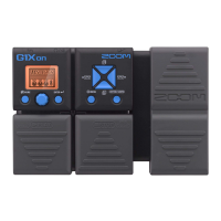
- 4 -
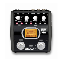
Function Test
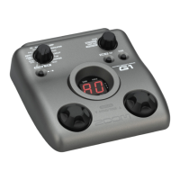
Starting in “Test mode”
1) Start up the G1 in the following ways using the AC adaptor AD-0006.
a) Connect AC adaptor holding the [BANK UP・TAP] key (SW1) and [RHYTHM] key (SW2).
b) Connect AC adaptor when Ground and the test point TP4.
*When set 4 batteries, connect the plug into INPUT connector (J2)
2) All the LEDs of 7 segment LED will be lit.
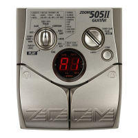
1. Display (7 segment LED)
1) Make sure that all LEDs are lit brightly enough (indicate “8.8.”) after power on in “Test mode”.
2) Press any key and make sure that all LEDs will be turned off.
2. Module selector
1) Turn the Module selector (VR1) clockwise to “DECAY”.
2) Turn the Module selector (VR1) anticlockwise by one detent.
Make sure that the following indications appear on the 7 segment LED.
Module selector 7 segment LED
DECAY/TIME 15
REVERB/DERAY 14
RATE/TIME 13
MODULATION/DELAY 12
ZNR/AMP 11
EQ_Hi 10
EQ_Mid 9
EQ_Lo 8
MIX 7
GAIN 6
DRIVE 5
EFX 4
COMP/LIMIT 3
PATCH LEVEL 2
RHYTHM 1
PLAY 0
3) Turn the Module selector (VR1) clockwise by one detent.
Make sure that the above values are indicated on the 7 segment LED depending on the
Module selector position.