- 5 -
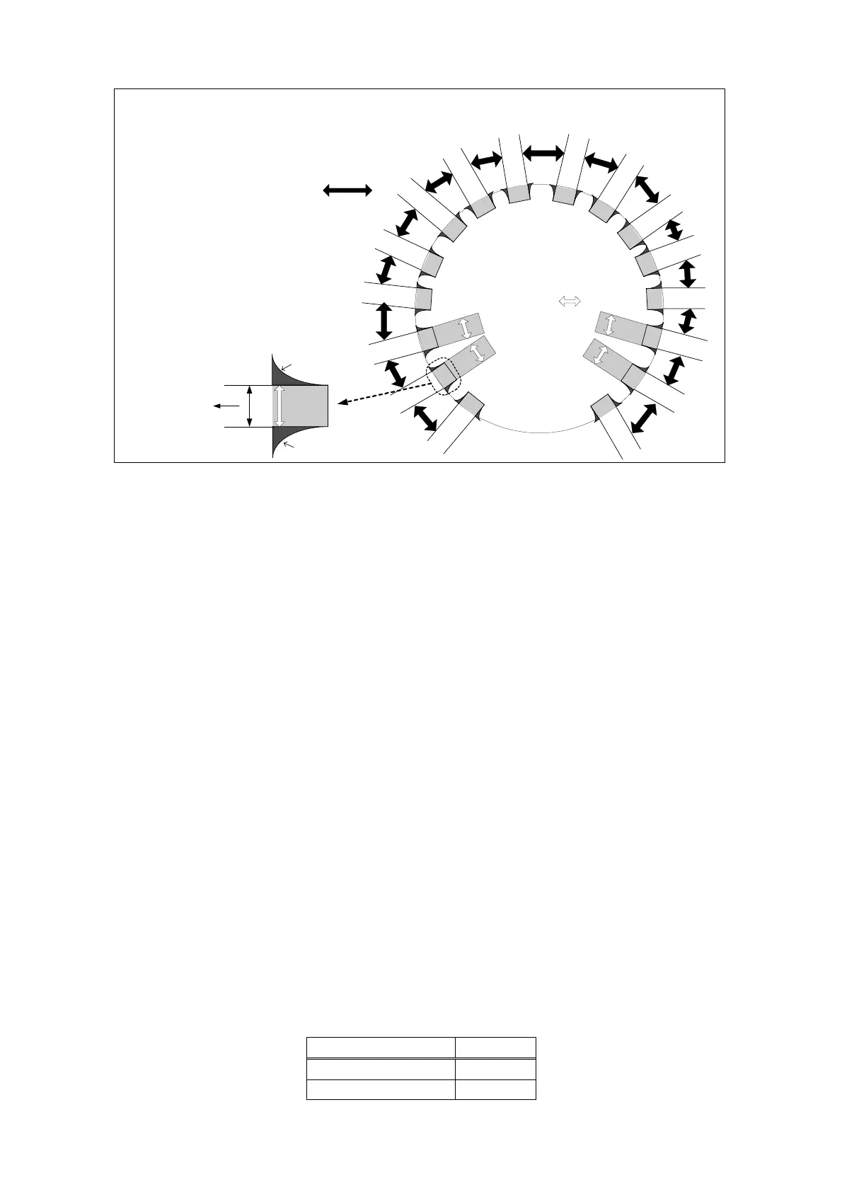
Figure 1.16 clicks value confirmation position
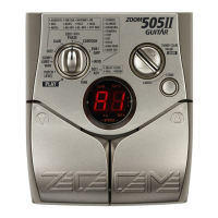
3. Knob
Turn the [VALUE] knob (SW6) and 7 segment LED indicates “00–FF”.
Make sure that indication smoothly changes in the range of “00-FF” and the value
changes 1 step by 1 detent.
4. Flash rom
Press the [BANK UP・TAP] key (SW1).
Make sure that “ok” appears on the 7 segment LED.
If any error occurs, “nG” is indicated on the 7 segment LED.
5. Product number
1)Press the FOOT SWITCH [^] (SW5).
Make sure that “G1” is indicated on the 7 segment LED.
2) Press the FOOT SWITCH [^] (SW5) again.
Make sure that “9b” is indicated on the 7 segment LED.
6. Foot pedal
1) Connect FP-01 or FP-02 with CONTROL IN connector (J1).
2) Move the expression pedal.
Make sure that the values on the display change as follows.
Expression pedal Values
MIN (raised) 05–0C
MAX (down) E3–FF
①
②
③
④
⑤
⑥
⑦
⑧
⑨
⑩
⑪
⑫
⑬
⑭
⑮
⑯
⑰
⑱
⑲
②④⑯⑱
※It is NG that a
value changes in a
click.
0
1
2
3
4
5
6
7 8
9
10
11
12
13
14
15
There is a change in
a click
(allowance)=
NG
It is OK to change with a
dark color.
It is OK to change with a
dark color.
①③⑤~⑮⑰⑲
※A value changes in
a range of arrow
Inspection judgment standard of 16 click setting.
0->1、2->1
13->14、15->14
Attention at the time
of setting
↓
allowance
It must
consciously setting
that center of
allowance.