- 9 -
Back Up User’s Data
If necessary, back up the user’s effect patch data to avoid an accidental erasing.
Required
· User’s G1X as a transmitter (hereinafter referred to as “the transmitter”)
· Another G1X as a receiver (hereinafter referred to as “the receiver”)
· Jumper wires
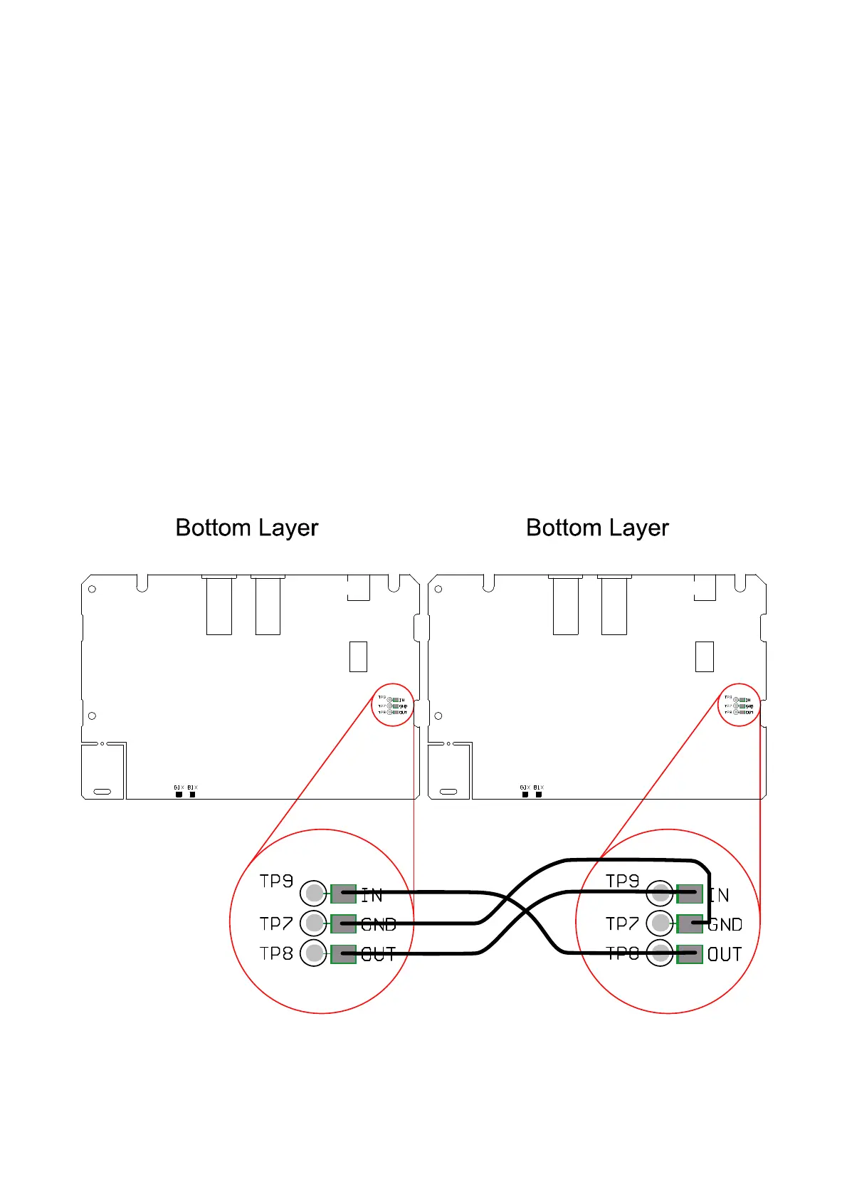
1. Remove the bottom plate.
2. Connect “IN” terminal of the transmitter and “OUT” terminal of the receiver.
3. Connect “OUT” terminal of the transmitter and “IN” terminal of the receiver.
4. Connect their ground terminals on the top side of the main PCB, using jumper wires (See
below).
Transmitter Receiver
Main PCB top side Main PCB top side
5. Turn on the power of both transmitter and receiver while holding the [STORE] (SW3) and
the [BANK UP・TAP] (SW1) keys.
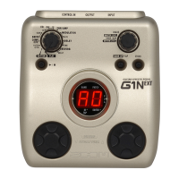
Make sure that the both 7segment LED lit "tr".

 Loading...