13
Hardware Installation
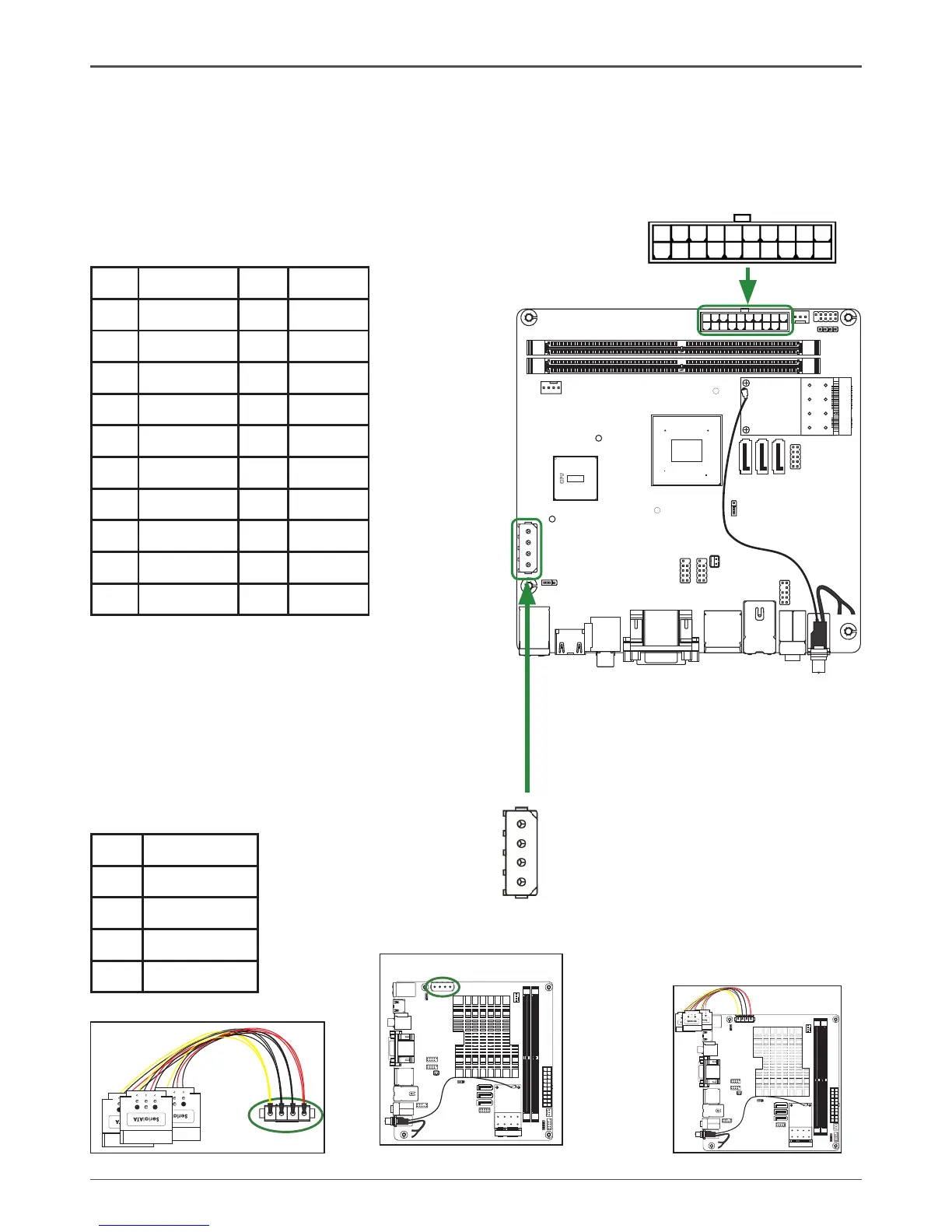
20-pin ATX Power-PW1(Optional)
PW1 is the main power supply connector located along the edge of the board next to
the DIMM slots. Make sure that the power supply cable and pins are properly aligned
with the connector on the motherboard. Firmly plug the power supply cable into the
connector and make sure it is secure.
110
1120
DC OUT Connector-CN7(Optional)
This motherboard can supply the power to
SATA devices with a SATA power cable,plug
a SATA power cable(as picture 7) to DC out
connector(as picture 8),at last as picture 9.
CN7-Pin Difinition
PIN Assignment
1 12V
2 GND
3 GND
4 5V
1
CN7
PW1-Pin Assignments
Pin Signal Pin Signal
1 +3.3V 11 +3.3V
2 +3.3V 12 -12V
3 GND 13 GND
4 +5V 14 PS_ON
5 GND 15 GND
6 +5V 16 GND
7 GND 17 GND
8 PWROK 18 -5V
9 +5V_AUX 19 +5V
10 +12V 20 +5V
 Loading...