EasyManuals Logo

Zotac ION ITX series User Manual

Zotac ION ITX series
58 pages
To Next Page IconTo Next Page
To Previous Page IconTo Previous Page
Page #7 background imageLoading...
Page #7 background image
6
ION ITX Series Motherboard
Motherboard Layout
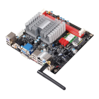
Figure 1 shows the motherboard and Figures 2 shows the back panel connectors.
Figure 1. Board Layout
1. 20-pin ATX Power Connector(Optional)
2. System Fan Connector
3. Front Panel Header
4. Speaker Header
5. Mini PCIE Slot
6. COM Header
7. Serial-ATA (SATA) Connectors
8. Clear CMOS Jumper
9. Chip Fan Connector
10. Front Audio Header
11. Backpanel Connectors
12. USB power Jumper
13. USB Headers
14. DC-OUT Connector(Optional)
15. CPU
16. Chipset
17. CPU Fan Connector
18. DDRII DIMM Sockets
120
240
121
120
240
121
+
.
.
.
CPU
K b
d
4
5
6
7
9
8
+
2
3
10
11
12
13
14 1516 17
18
Ke
yboard
/USB
HDM
I
SPDIF-
OUT
JP3
D
VI/VG
A
eS
ATA
/USB
LA
N/US
B
SD1
PT3
Front Audio
-FP_S1
CHIP_FAN- J2505
Clear CMOS
-JP1
SATA1
SATA21
SATA3
COM
Chiset
USB-FP_U2
USB-FP_U1
DC OUT-DN7
C_F
AN
1
DDRII1
DDRII2
2 52
51
20
pi
n A
TX
Po
wer-PW1
S_F
AN
1
FP
1
S
PK1
Mini PCIE

Questions and Answers:

Question and Answer IconNeed help?

Do you have a question about the Zotac ION ITX series and is the answer not in the manual?

Zotac ION ITX series Specifications

General IconGeneral
BrandZotac
ModelION ITX series
CategoryMotherboard
LanguageEnglish

Related product manuals