13
Hardware Installation
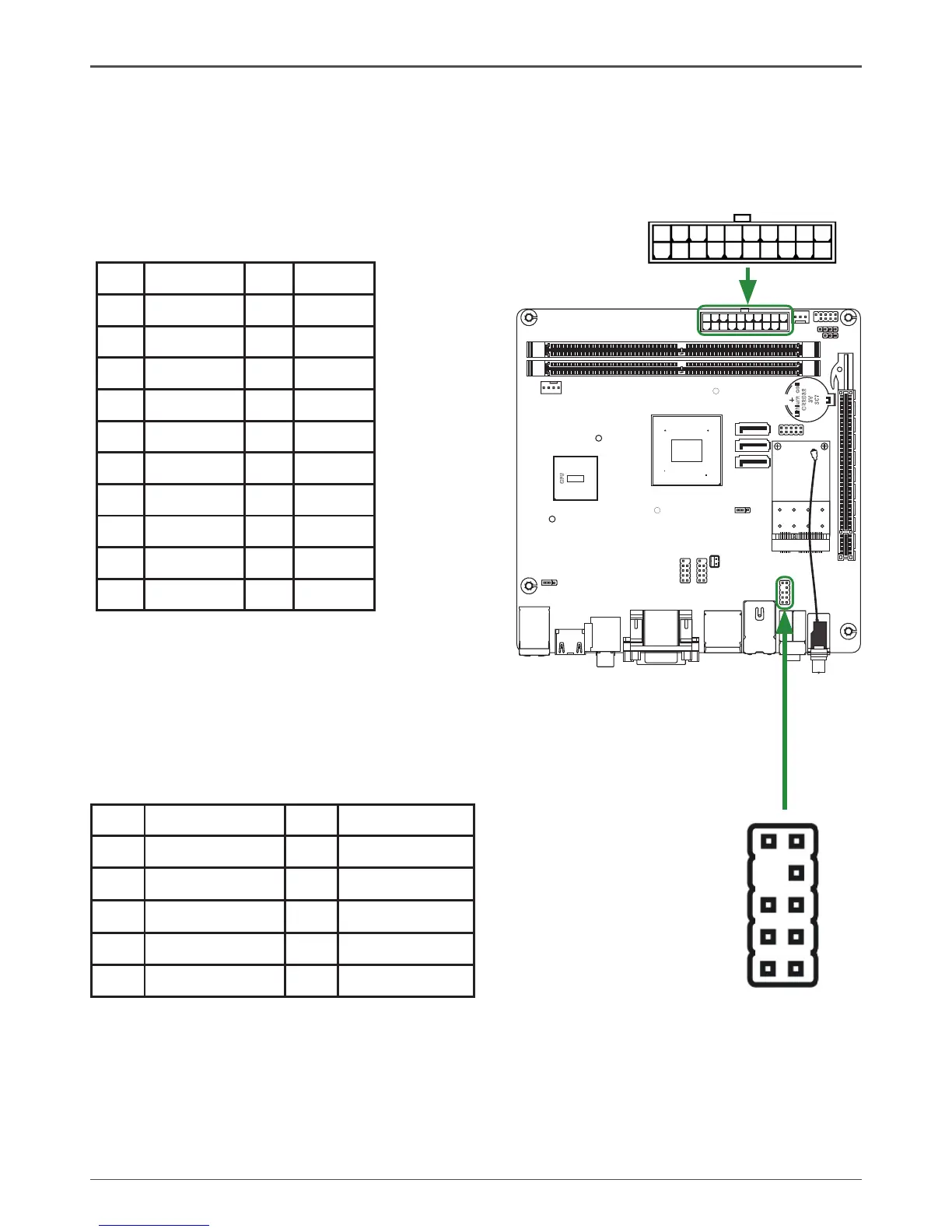
20-pin ATX Power-PW1
PW1 is the main power supply connector located along the edge of the board next to
the DIMM slots. Make sure that the power supply cable and pins are properly aligned
with the connector on the motherboard. Firmly plug the power supply cable into the
connector and make sure it is secure.
ATXPWR-Pin Assignments
Pin Signal Pin Signal
1 +3.3V 11 +3.3V
2 +3.3V 12 -12V
3 GND 13 GND
4 +5V 14 PS_ON
5 GND 15 GND
6 +5V 16 GND
7 GND 17 GND
8 PWROK 18 -5V
9 +5V_AUX 19 +5V
10 +12V 20 +5V
Front Audio Header-FP_S1
The audio connector supports HD audio standard and provides two
kinds of audio output choices: the Front Audio, the Rear Audio. The
front Audio supports re-tasking function.
Note:
In order to utilize the front audio header, your chassis must have front audio connector.
Also please make sure the pin assignment on the cable is the same as the pin assignment
on the mainboard header. To find out if the chassis you are buying supports a front audio
connector, please contract your dealer.
FP Audio-Pin Definition
PIN Assignment PIN Assignment
1 MIC2(L) 6 Reserved
2 GND 7 FAVDIO-JD
3 MIC(R) 8 Key(No pin)
4 -ACZ-DET 9 Front Audio(L)
5 Front Audio(R) 10 Reserved
110
1120 PW1
2
1
10
9
FP_S1
 Loading...