EasyManuals Logo

Zotac IONITX-F series User Manual

Zotac IONITX-F series
54 pages
To Next Page IconTo Next Page
To Previous Page IconTo Previous Page
Page #9 background imageLoading...
Page #9 background image
8
NVIDIA ION PCIEx16 series Motherboard
236 -D A1 23 -x x0 1F
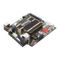
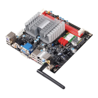
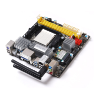
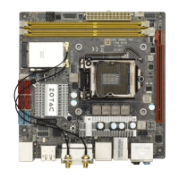
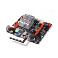
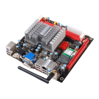
Remove the red antenna connector cover(as picture 1), install the antenna to the connector
and make sure that screw down clockwise(as picture 2),at last as picture 3.
120
240
121
+
CPU
Lith ium cel l
CR20 32
3V
SC 7
120
240
121
6
According to your requirement modulate to the
antenna as right picture.
6
11
5
10
15
4
5
6
11
5
10
15
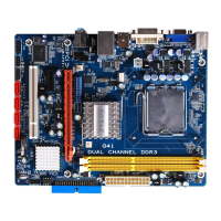
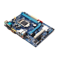
10. WiFi antenna connctor(Optional)
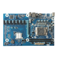
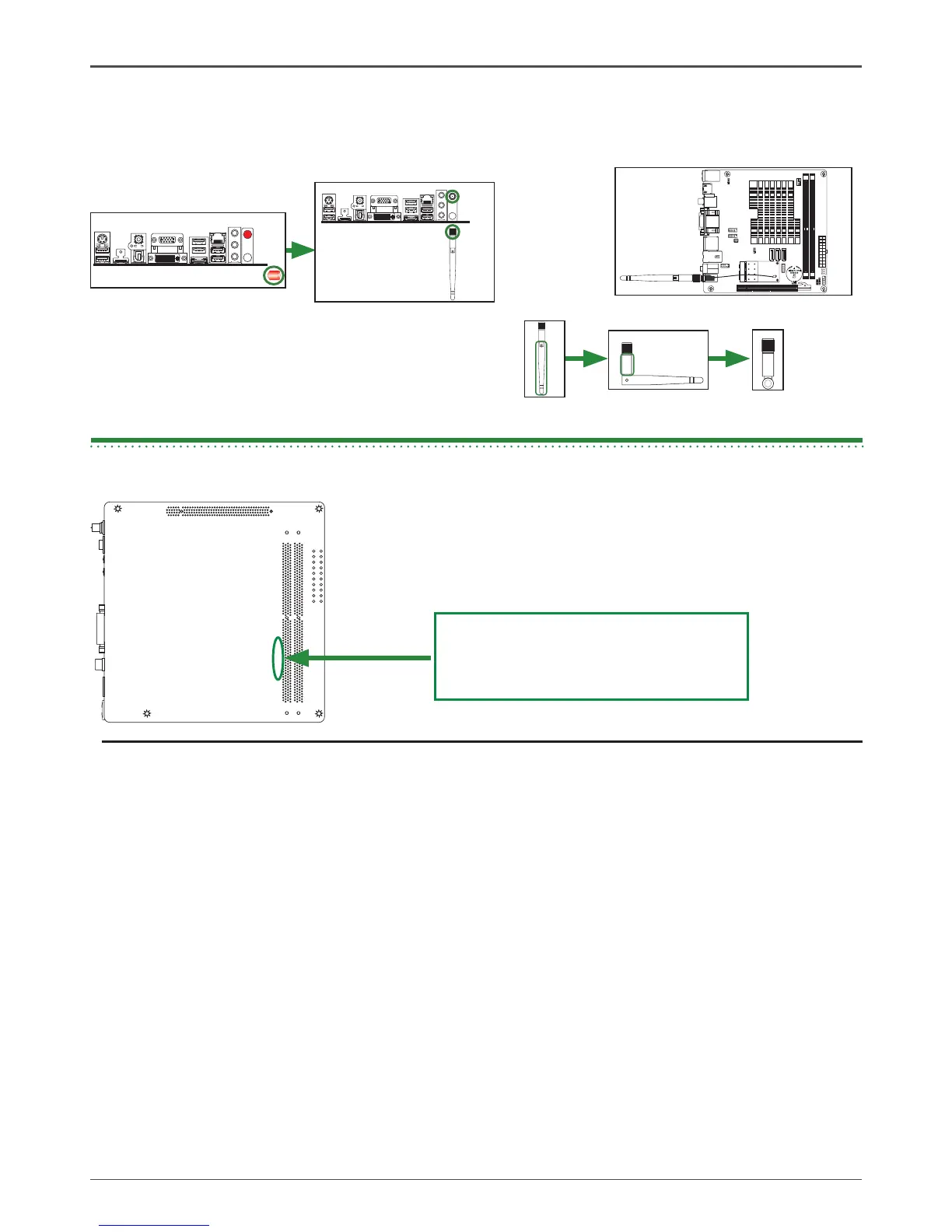
The bottom side of motherboard PCB
shows “236-DA123-xx01F”
Motherboard PCB Version:01
Note:
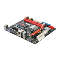
* Different motherboard PCB version could carry slightly different features and components
placement . Please refer to the following diagram to identify PCB version:
* How to identify PCB Versionto identify PCB Version PCB Version

Table of Contents

Questions and Answers:

Question and Answer IconNeed help?

Do you have a question about the Zotac IONITX-F series and is the answer not in the manual?

Zotac IONITX-F series Specifications

General IconGeneral
BrandZotac
ModelIONITX-F series
CategoryMotherboard
LanguageEnglish

Related product manuals