Getting to know your ZOTAC MAG
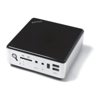
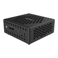
Headphone/Audio 1.
Out jack - The
stereo headphone
jack (3.5mm) is
used to connect
the system’s audio
output to amplified
speakers or head-
phones.
Microphone jack2. - The microphone jack is designed to connect a microphone used for video conferencing, voice nar-
rations or simple audio recordings.
Memory card reader3. - The built-in memory card reader is compatible with SD/MS/MS Pro/XD cards used in devices
like digital cameras, MP3 players, mobile phones and PDAs.
USB 2.0 ports4. - The USB (Universal Serial Bus) port is compatible with USB devices such as keyboards, mouse
devices, cameras and hard disk drives. USB ports allow many devices to run simultaneously on a single computer,
with some peripherals acting as additional plug-in sites or hubs.
WiFi LED 5. - The WiFi LED blinks when data is being transfered over WiFi.
Hard drive LED6. - The hard drive LED blinks when data is being written to or read from the hard disk drive.
Power button 7. - The power switch powers the system ON and OFF.
Refer to the diagram below to identify the components on the front of the system
Front view
1 2 3 4 5 6 7
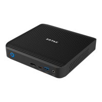
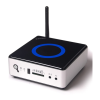
eSATA1. - The
external SATA port
is compatible with
e.SATA devices
such as external
hard drives and
Blu-ray drives.
USB 2.0 port2. - The
USB (Universal
Serial Bus) port is compatible with USB devices such as keyboards, mouse devices, cameras and hard disk drives.
USB allows many devices to run simultaneously on a single computer, with some peripherals acting as additional
plug-in sites or hubs.
LAN port3. - The eight-pin RJ-45 LAN port supports standard Ethernet cables for connection to a local network.
VGA port4. - The VGA port supports connection to analog monitors and displays.
HDMI port5. - The HDMI (High Definition Multimedia Interface) port supports a Full-HD device such as an LCD TV or
monitor to allow viewing on a larger external display.
Optical S/PDIF output jack6. - Plug an optical cable into this jack for digital audio transfer to a stereo receiver or
speakers.
Power input (DC19V)7. - The supplied power adapter converts AC power to DC power for use with this jack. Power sup-
plied through this jack supplies power to the PC. To prevent damage to the PC, only use the supplied power adapter.
Note: the power adapter may become warm to hot when in use. Do not cover the adapter and keep it away from your body.
Refer to the diagram above to identify the components on the rear of the system
Rear view
1 2 3 4 5 6 7
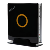
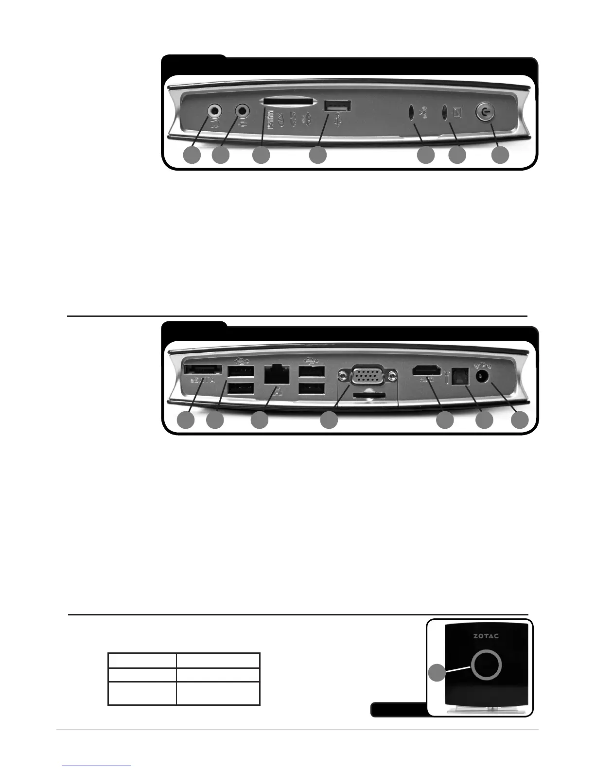
Status LED1. - The yellow status LED reports the ACPI functions of the
system. The different displays the LED can display is as follows:
System is on LED is on
System is off LED is off
System is in
standby mode
LED flashes slowly
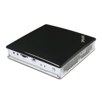
Side view
1